Low emissions diesel piston

Active Publication Date: 2008-06-24
GM GLOBAL TECH OPERATIONS LLC
View PDF16 Cites 19 Cited by
  • Summary
  • Abstract
  • Description
  • Claims
  • Application Information

AI Technical Summary

Benefits of technology

[0004]The present invention provides an improved diesel engine combustion bowl design that allows for enhanced mixing of combustion products with excess air available in the cylinder, simultaneously reducing soot and NOx emissions. More particularly, the present invention provides a piston having an improved bow

Problems solved by technology

Exhaust aftertreatment systems, however, can be costly and therefore

Method used


Image

  • Low emissions diesel piston
  • Low emissions diesel piston
  • Low emissions diesel piston

Examples


Embodiment Construction

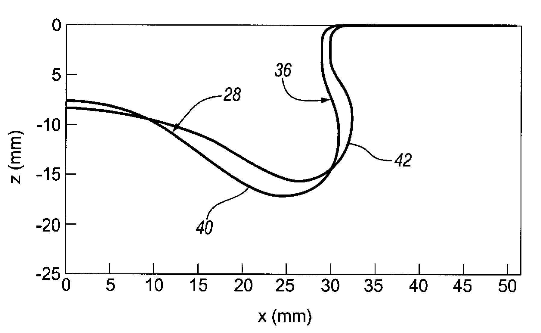
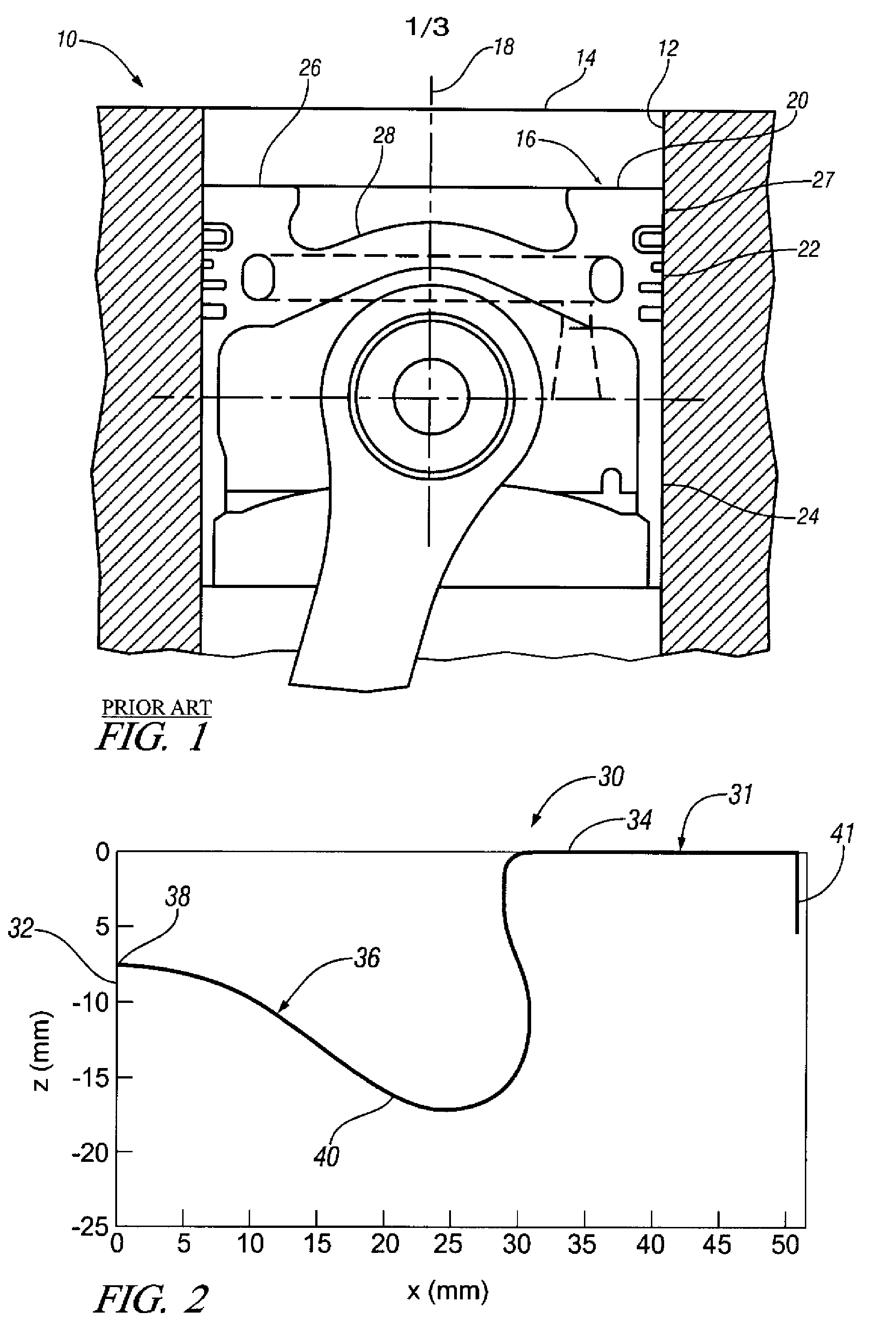
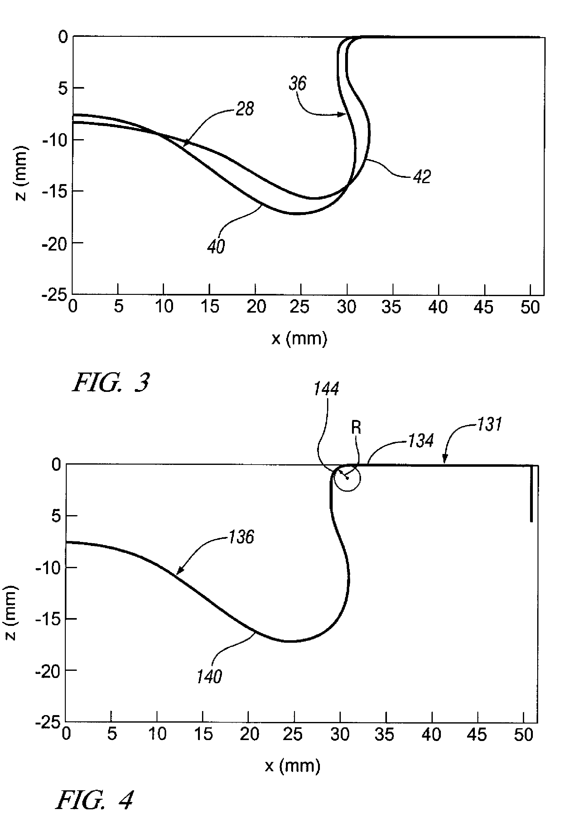
[0014]Referring first to FIG. 1 of the drawings, numeral 10 generally indicates a known diesel engine including a cylinder 12 having a closed upper end 14. A prior art piston 16 is reciprocable in the cylinder 12 along a central axis 18. The piston 16 generally has a cylindrical shape centered on the axis 18 and includes a crown 20, a ring belt 22 with piston ring grooves and a skirt 24 extending axially from the ring belt 22. The crown 20 has a generally planar upper rim 26 extending inward from a side wall 27 and generally defining the top of the piston 16. A circular combustion bowl 28 is recessed in the crown 20 within the crown rim 24 and centered on the central axis 18. Fuel sprayed from a fuel injector (not shown) is sprayed from the central axis 18 out toward the edge of the combustion bowl 28. The present invention relates to an improved configuration for a combustion bowl for use in place of the bowl 28 shown in the prior art piston 16.

[0015]Referring to FIG. 2, a piston 3...


PUM


Abstract

A piston for a diesel engine has a crown and a three-dimensional shape defined in an x-y-z coordinate space. The z-axis generally defines a cylinder axis of the piston, and the plane z=0 generally intersects an upper rim of the crown. The piston includes a combustion bowl recessed in the crown. The combustion bowl has a center point on the z-axis and has a two-dimensional partial cross-sectional configuration defined by a peripheral line connecting coordinate points (xi,yi,zi) in the x-y-z coordinate space. The (xi,yi,zi) coordinate points include points from a coordinate set S. The combustion bowl has a three-dimensional axisymmetric configuration defined by rotating the peripheral line 360° about the z-axis.

Description

TECHNICAL FIELD[0001]This invention relates to a diesel engine piston having an improved combustion bowl configuration.BACKGROUND OF THE INVENTION[0002]It is known in the art relating to diesel engines that future governmental emissions regulations require improvements in engine design in order to reduce emissions to meet or exceed these regulations. For example, enhanced air system designs could provide higher rates of cooled EGR (exhaust gas recirculation), thereby reducing NOx emissions, while enhanced fuel injection systems could reduce the inevitably higher soot emissions that would result from the use of higher EGR rates. Also, combined soot and NOx emissions aftertreatment systems could reduce emissions from diesel engines. Exhaust aftertreatment systems, however, can be costly and therefore are not the most desirable means of achieving emissions reductions.[0003]In contrast, advancements in the combustion system design could reduce emissions while minimizing the need for cos...

Claims


Application Information

Patent Timeline
IPC IPC(8): F02F3/14F02F3/26
CPCF02B23/0672F02B3/06Y02T10/125Y02T10/12
Inventor WICKMAN, DAVID D.CHANG, SHENGMINGDIWAKAR, RAMACHANDRA
Owner GM GLOBAL TECH OPERATIONS LLC
Why Eureka
Try Eureka