Tool for chip removing machining, and a basic body and a lock member therefor

a technology for removing tools and cutting inserts, which is applied in the direction of turning machine accessories, manufacturing tools, shaping cutters, etc., can solve the problems of inability to use traditional cutting tools to generate the proper surfaces, inability to achieve alternative realistic, and difficulty in forming countersinks, etc., to minimize the risk of unintentional rotation of cutting inserts and improve the rotational securing of cutting inserts

Inactive Publication Date: 2008-06-24
SANDVIK INTELLECTUAL PROPERTY AB
View PDF17 Cites 52 Cited by
  • Summary
  • Abstract
  • Description
  • Claims
  • Application Information

AI Technical Summary

Benefits of technology

[0008]In an embodiment of the invention, the planar shoulder surface or surfaces, which co-operate with the planar engagement surfaces of the cutting insert, are formed in a separate lock member instead of in a countersink, which has to be accomplished by chip removing machining in the basic body. The separate lock member can in a simple way be made in a machining operation that is separate from the manufacture of the basic body, and can then be mounted in a space that is formed in the basic body in a simple and fast way.

Problems solved by technology

However, if the milling cutter should be equipped with small cutting inserts, and in particular, many small cutting inserts, difficulties arise in forming the countersink.
In such cases, the plurality of (e.g., six) planar shoulder surfaces, which together form the countersink, will become so exceptionally small that traditional cutting tools cannot be used to generate the proper surfaces, as well as the requisite clearances between the same.
Studies made on the question whether it would be possible to mill cut the surfaces by means of special shank-end mills having a diameter of down to 1 mm have shown that this alternative is not realistic.

Method used


Image

  • Tool for chip removing machining, and a basic body and a lock member therefor
  • Tool for chip removing machining, and a basic body and a lock member therefor
  • Tool for chip removing machining, and a basic body and a lock member therefor

Examples


Embodiment Construction

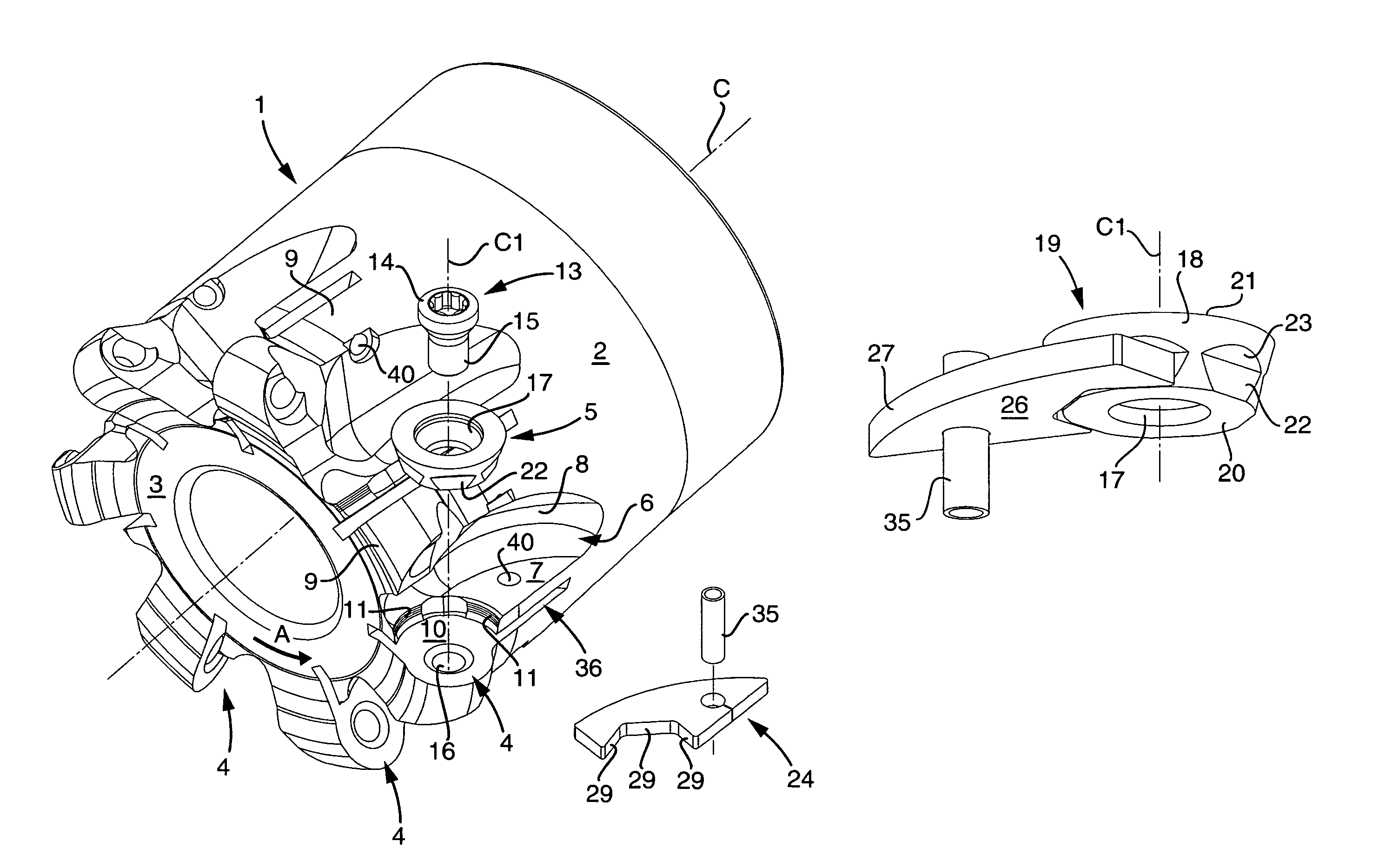
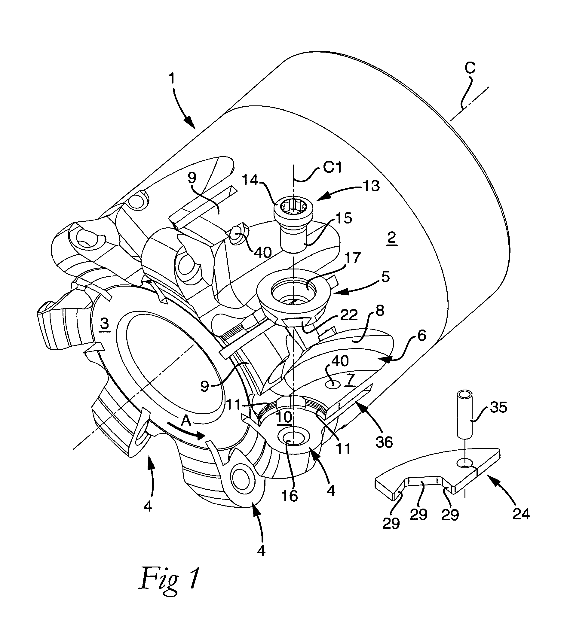
[0020]Below, an embodiment of the invention will be described in connection with a rotatable cutting tool in the form of a milling cutter for chip removing metal machining and including a plurality of cutting inserts and insert seats. However, the invention also applies to other cutting tools, e.g., fixed turning tools having only one or a few cutting inserts and insert seats, respectively.

[0021]The milling cutter shown in FIG. 1 includes a basic body 1 that is rotatable around a center axis C and has an envelope surface 2 having a rotationally symmetrical, in this case cylindrical, shape, and a planar, ring-shaped front end surface 3. In the transition between the envelope surface 2 and the front end surface 3, a number of peripherally separated insert seats 4 are formed, which receive cutting inserts 5, only one of which is shown in FIG. 1. In the rearward direction from each individual insert seat 4, a chip pocket 6 extends, which in this case is delimited by a planar, shelf-like...


PUM

PropertyMeasurementUnit
angleaaaaaaaaaa
diameteraaaaaaaaaa
angleaaaaaaaaaa

Abstract

A tool for chip removing machining, including a basic body and a replaceable cutting insert that has a center axis and is detachably mounted in an insert seat formed in the basic body. The seat is delimited by a bottom surface and at least one side support surface. The cutting insert includes an out of round engagement surface that is pressed against an out of round shoulder surface to rotationally secure the cutting insert. The shoulder surface is included in a separate lock member that is partially inserted in a space formed in the basic body, the space opening towards the insert seat and located between the side support surface and the bottom surface of the insert seat such that the lock member rotationally secures a lower part of the cutting insert, while an upper part of the cutting insert is supported by the side support surface.

Description

[0001]This application claims priority under 35 U.S.C. § 119 to Sweden Patent Application No. 0502832-9, filed on Dec. 21, 2005, the disclosure of which is incorporated by reference herein in its entirety.FIELD OF THE INVENTION[0002]The present invention relates generally to a tool for chip removing machining of the type that includes a basic body and a replaceable cutting insert that has a geometric center and is detachably mounted in an insert seat formed in the basic body, which seat is delimited by a bottom surface and at least one side support surface, the cutting insert including an out of round engagement surface that is pressed against a likewise out of round shoulder surface in order to rotationally secure the cutting insert. The invention also relates to a basic body and a lock member, respectively, for such tools.BACKGROUND OF THE INVENTION[0003]Milling cutters may be equipped with a plurality of small and round cutting inserts that are generally pulley-shaped and have a ...

Claims


Application Information

Patent Timeline
Patent Type & Authority Patents(United States)
IPC IPC(8): B23C5/22
CPCB23C5/06B23C5/2204B23C5/2239B23C5/2265B23C2200/045Y10T407/2272B23C2200/168B23C2210/168Y10T407/23Y10T407/2202Y10T407/191B23C2200/125B23B27/1614B23C5/2226B23C5/2306
Inventor WIHLBORG, LENNART
Owner SANDVIK INTELLECTUAL PROPERTY AB
Why Eureka
Try Eureka