

Magnetically coupled heat dissipating fan
a heat dissipating fan and magnetocoupling technology, applied in the direction of positive displacement liquid engines, piston pumps, liquid fuel engines, etc., can solve the problems of great noise and heat dissipation fans b>20/b> in an inverted state, and achieve the effect of avoiding the noise of tangential wind effects
- Summary
- Abstract
- Description
- Claims
- Application Information
AI Technical Summary
Benefits of technology
Problems solved by technology
Method used
Image

Examples
first embodiment
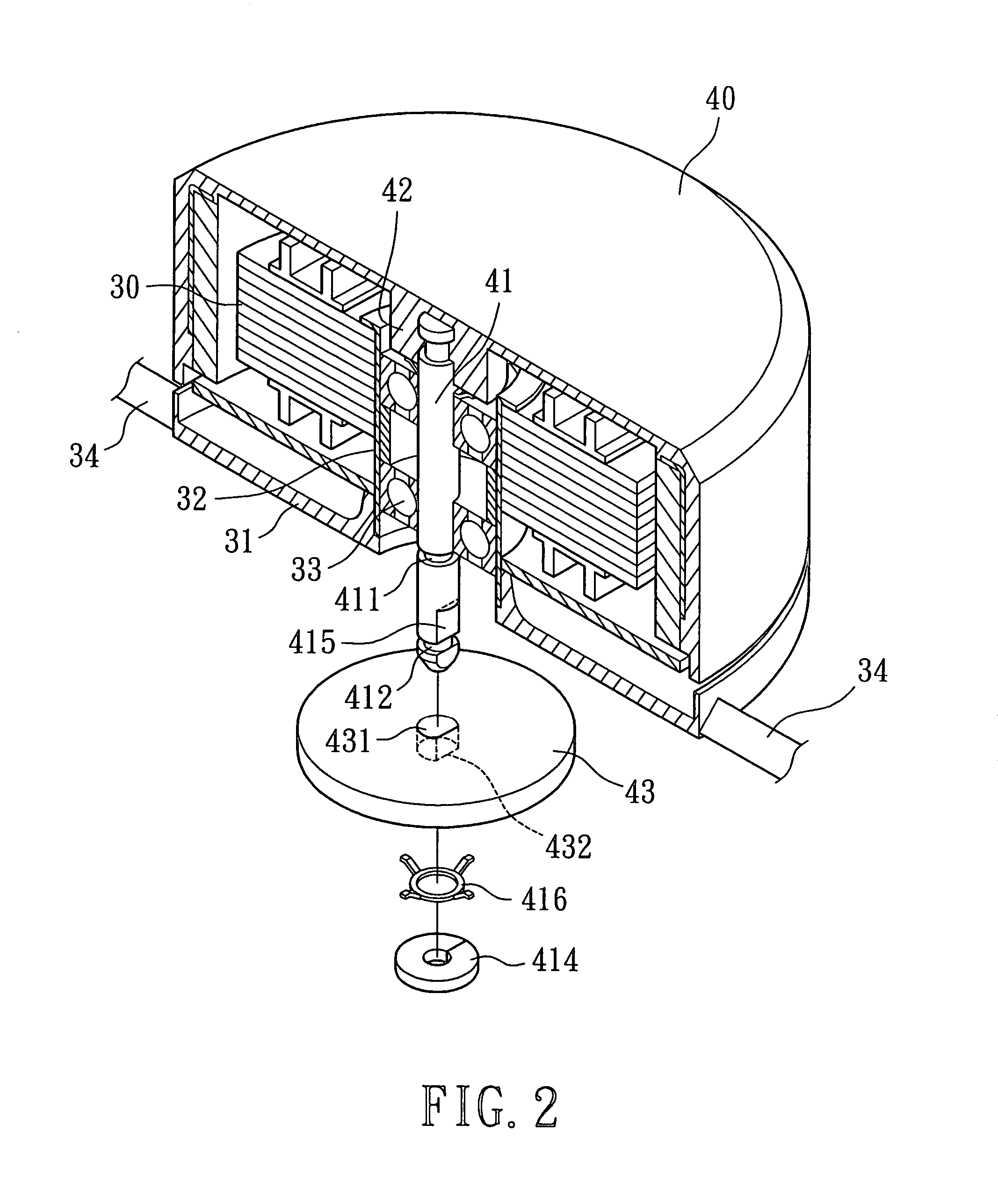
[0026]Referring to FIGS. 2 and 3, a heat-dissipating fan in accordance with the present invention comprises a casing 35 in which a stator 30 and an impeller 40 are mounted. The casing 35 includes a base 31 that is connected to and thus supported by a plurality of ribs 34 between the base 31 and an inner circumferential wall of the casing 35. The base 31 includes an axial tube 32 at a center thereof, and a bearing 33 is mounted in the axial tube 32. The stator 30 is mounted around the axial tube 32.
[0027]A plurality of vanes 401 extend from an outer circumferential wall of the impeller 40. The impeller 40 includes an axial seat 42 at a center thereof. A first end of a shaft 41 is fixed to the axial seat 42. The shaft 41 is rotatably extended through the bearing 33. A magnetic member 43 is mounted to a second end of the shaft 41 extending through the bearing 33. Thus, the impeller 40 is mounted around the stator 30 and the impeller 40 is driven to turn through magnetic energizing.
[002...
second embodiment
[0030]FIGS. 5 and 6 illustrate a second embodiment for fixing the magnetic member 44 and the shaft 41. In this embodiment, the shaft 41 also includes a flat surface 415 in a section of an outer circumference of the shaft 41 adjacent to the second annular groove 412. Thus, the shaft 41 is non-circular in this section. The magnetic member 44 includes a non-circular axial hole 441 in a center thereof through which the shaft 41 extends. The non-circular hole 441 includes a flat section 442 for engaging with the flat surface 415 of the shaft 41. Further, a recess 443 is defined in a bottom side of the magnetic member 44 for receiving the spring 416. Thus, the magnetic member 44 and the shaft 41 rotate synchronously after the second retaining member 414 is mounted into the second annular groove 412.
third embodiment
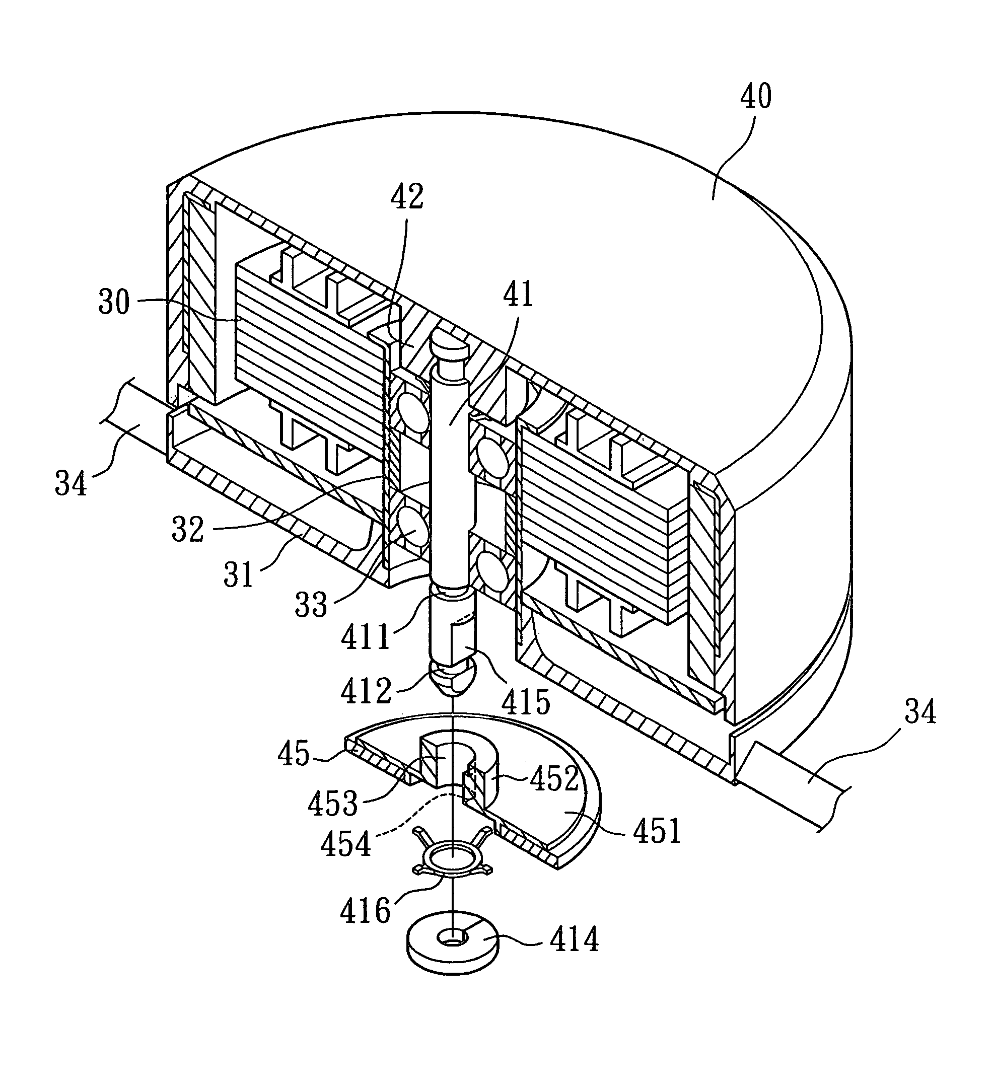
[0031]FIGS. 7 and 8 illustrate a third embodiment for fixing the magnetic member 45 and the shaft 41. In this embodiment, the magnetic member 45 is engaged with the shaft 41 via a magnet base 451. The magnetic member 45 is fixed below the magnet base 451 that includes a fixing seat 452 at a center thereof. An axial hole 453 is defined in a center of the fixing seat 452, and the shaft 41 is extended through the axial hole 453. The shaft 41 also includes a flat surface 415 in a section of an outer circumference of the shaft 41 adjacent to the second annular groove 412. Thus, the shaft 41 is non-circular in this section. The axial hole 453 includes a flat section 454 for engaging with the flat surface 415 of the shaft 41. Further, a recess (not labeled) is defined in a bottom side of the magnet base 451 for receiving the spring 416. Thus, the magnet base 451, the magnetic member 45, and the shaft 41 rotate synchronously after the spring 416 and the second retaining member 414 are mount...
PUM
 Abstract
Description
Claims
Application Information