
Sensor signal conditioning circuit

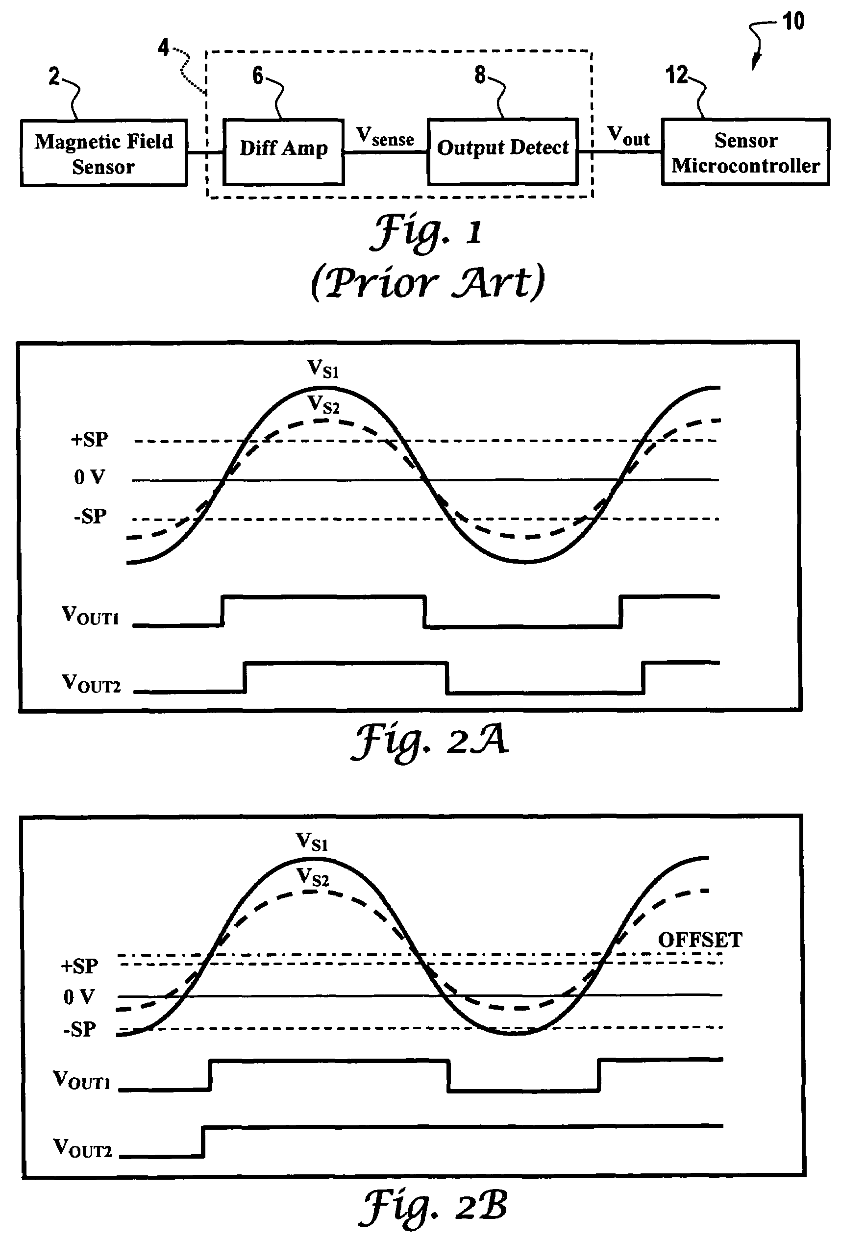
a technology of signal conditioning circuit and sensor, which is applied in the direction of code conversion, instrumentation, and computation operations for integration/differentiation, etc., can solve problems such as start-up delay

Inactive Publication Date: 2008-06-24
HONEYWELL INT INC
View PDF11 Cites 27 Cited by
  • Summary
  • Abstract
  • Description
  • Claims
  • Application Information

AI Technical Summary

Benefits of technology

This approach effectively eliminates DC offset, enabling precise and reliable sensor output tracking during startup and steady-state operation, reducing switch point errors and maintaining high bandwidth while avoiding capacitive charge-up delays.

Problems solved by technology

An AC-coupled detector having a dynamic DC threshold input also converts the sensor signal into a discrete level signal and has a startup delay associated with the dynamic DC threshold input.

Method used


Image

  • Sensor signal conditioning circuit
  • Sensor signal conditioning circuit
  • Sensor signal conditioning circuit

Examples


Embodiment Construction

[0023]The present invention is described in a preferred embodiment in the following description with reference to the figures. While this invention is described in terms of the best mode for achieving this invention's objectives, it will be appreciated by those skilled in the art that variations may be accomplished in view of these teachings without deviating from the spirit or scope of the present invention.

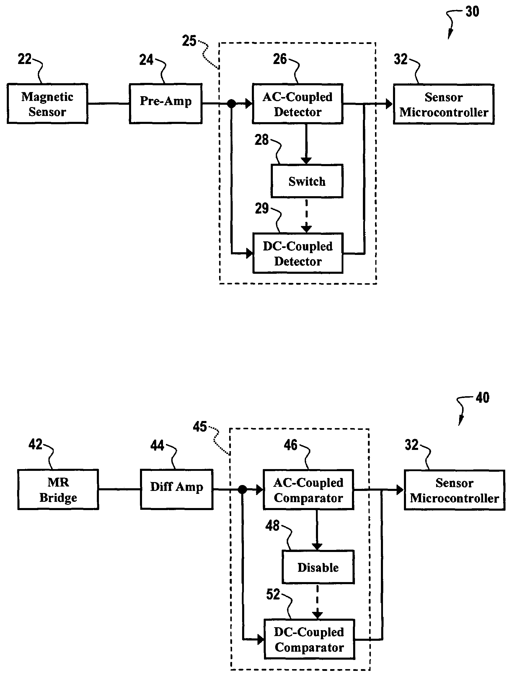
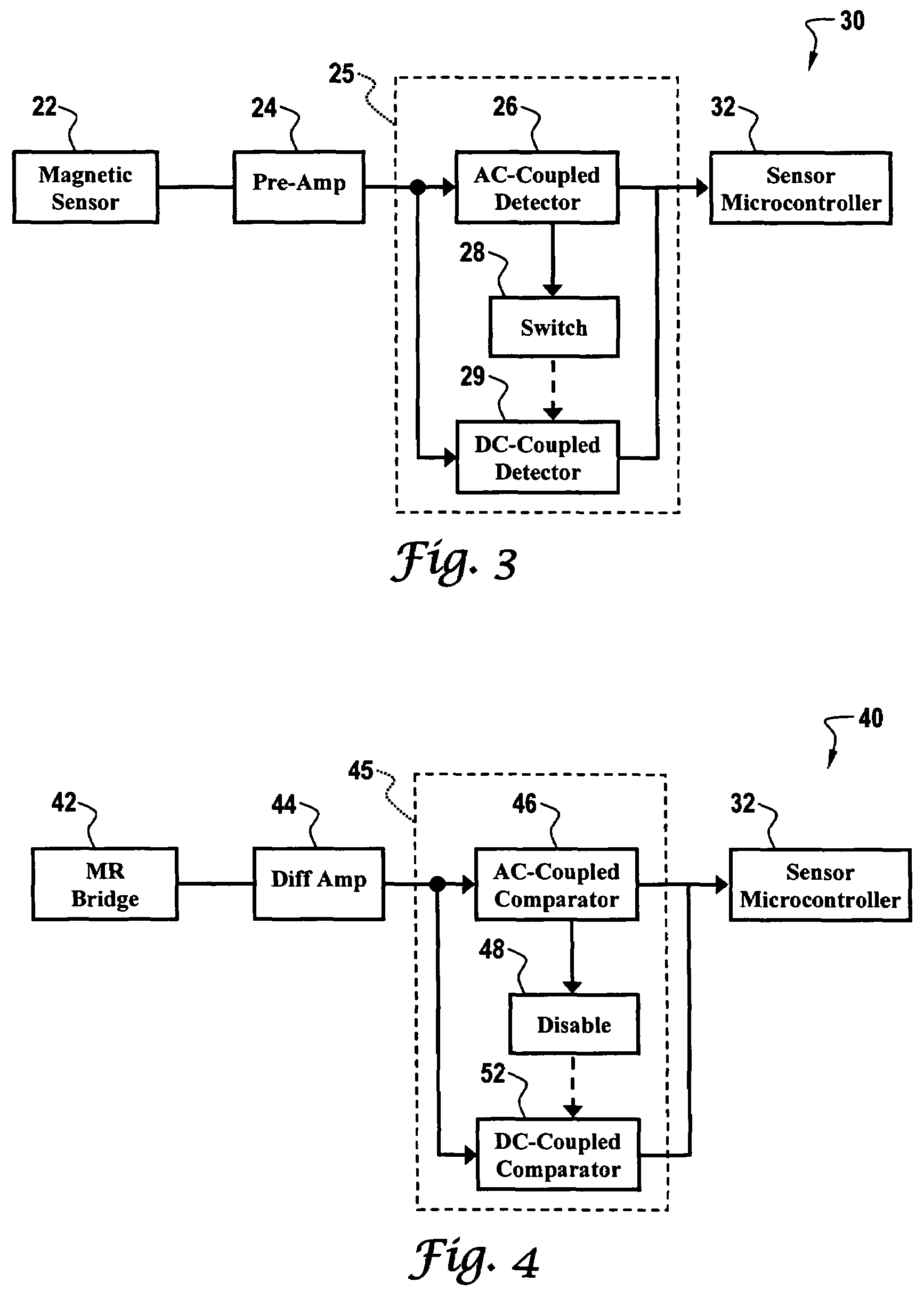
[0024]Embodiments are generally directed toward a signal conditioning circuit that employs an AC-coupling technique in order to substantially eliminate DC offset of a typically amplified analog sensor output signal. In a preferred embodiment, near zero DC offset of the sensor signal can be accomplished, enabling the detector / comparator switch points to be set as near the zero reference. The reduced switch point span results in substantially reduced switch point error when sensor output signal amplitude is altered such as by variations in sensor-to-magnetic element air gap. The p...


PUM


Abstract

A sensor signal conditioning circuit and sensor system incorporating the same. In one embodiment, the signal conditioning circuit includes a DC-coupled detector that converts a sensor signal into a discrete level signal. An AC-coupled detector having a dynamic DC threshold input also converts the sensor signal into a discrete level signal and has a startup delay associated with the dynamic DC threshold input. The signal conditioning circuit further includes a device that inhibits the DC-coupled detector responsive to the dynamic DC threshold input reaching a specified threshold voltage level such that the AC-coupled detector provides the detected output during steady-state sensor operation.

Description

TECHNICAL FIELD[0001]Embodiments are generally related to sensor signal conditioning circuits, and more particularly to a signal conditioning circuit that enables AC coupling of a sensor output signal to a threshold detection device while eliminating startup delay. More particularly, embodiments are related to a magnetic sensor device employing switched mode comparator functionality, wherein a DC-coupled comparator initially detects sensor output during startup and an AC-coupled comparator is thereafter utilized for providing superior switching point offset characteristics.BACKGROUND OF THE INVENTION[0002]Voltage comparison circuits are used in many different applications that are well known to those skilled in the art. One application for voltage comparison circuits is to detect the sensed output voltage from a geartooth magnetic sensor that utilizes a plurality of magnetoresistors connected in a Wheatstone bridge arrangement. Typical MR bridge sensors employ four magnetoresistors ...

Claims


Application Information

Patent Timeline
Patent Type & Authority Patents(United States)
IPC IPC(8): G01R33/04G01R33/12G01D5/244
CPCG01D5/24476G01D5/2448
Inventor BICKING, ROBERT E.
Owner HONEYWELL INT INC
Learn More