System and method for inspecting patterned devices having microscopic conductors

Active Publication Date: 2008-06-24
ORBOTECH LTD
View PDF13 Cites 9 Cited by
  • Summary
  • Abstract
  • Description
  • Claims
  • Application Information

AI Technical Summary

Benefits of technology

[0007]One embodiment of the system of the present invention seeks to distinguish between cut and dust defects on an FPD (flat panel display) panel. Both types of defects appear as dark spots in bright-field illumination and appear as bright in dark-field illumination. A preferred embodiment of the present invention achieves the distinction between cut and dust defects by analyzing cut brightness which is very sensitive to the azimuthal direction of illumination whereas dust defects appear bright independent of illumination direction. Preferably, the panel is illuminated simultaneously from a plurality of directions by various colors, thereby to facilitate human visualization and machine analysis of the nature of a seeming defect and keeping inspection time as short as possible. As a result of the multi-directional, multi-spectral illumination of the panel, cut defects have one specific color strongly dependent on their orientation, while dust defects appear as having both colors i.e. having a composite color. The obtained color image may be further analyzed for each color particularly.
[0008]A preferred embodiment of the present invention seeks to improve classification of different types of defects observed on an FPD panel and more particularly seeks to distinguish between cut and dust defects. During FPD fabrication, many active layers may be formed on a single glass plate. Ability to identify the defect type may indicate a problem in a production line. The output of the system of the present invention allows the production line to be fixed appropriately, thus increasing production yield.
[0010]Preferably, the panel is illuminated simultaneously from a plurality of directions by various colors, different colors being associate with different azimuthal directions, which facilitates human visualization of defect nature, automatic classification and minimization of inspection time. As a result, cut defects have predominant color strongly dependent on orientation, while dust defects appear as a mixture or composite of both or all colors used preferably being such as to be distinguishable and discernable by a human operator or in machine analysis. The resulting color picture can be disassembled into corresponding 1-color figures for further computerized analysis. Since an FPD panel generally comprises known line orientations (e.g. in directions: 0°, 90°, 45° and 135°), the illuminator typically comprises two groups of illuminator units e.g. light emission diodes or optical fibers, arranged in parallel to the known line orientations of the workpiece or panel e.g. along the (0°) and (90°) axes, and the (45°) and (135°) axes, to cover all possible angles.

Problems solved by technology

Ability to identify the defect type may indicate a problem in a production line.

Method used


Image

  • System and method for inspecting patterned devices having microscopic conductors
  • System and method for inspecting patterned devices having microscopic conductors
  • System and method for inspecting patterned devices having microscopic conductors

Examples


Embodiment Construction

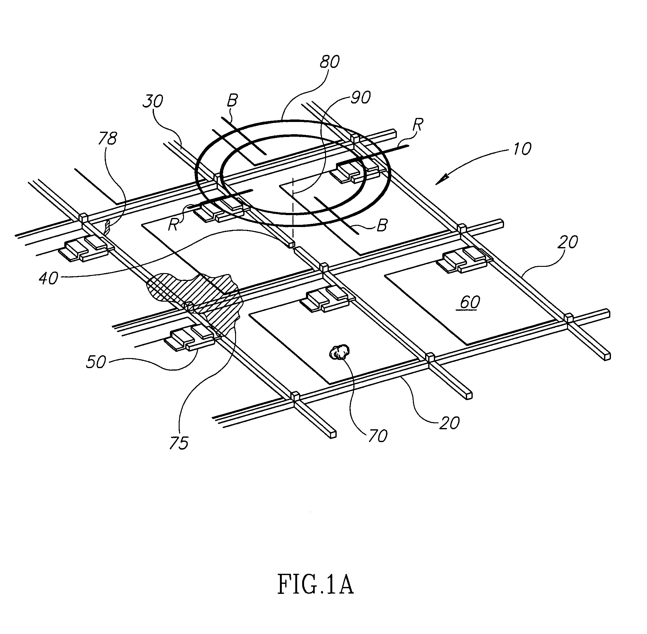
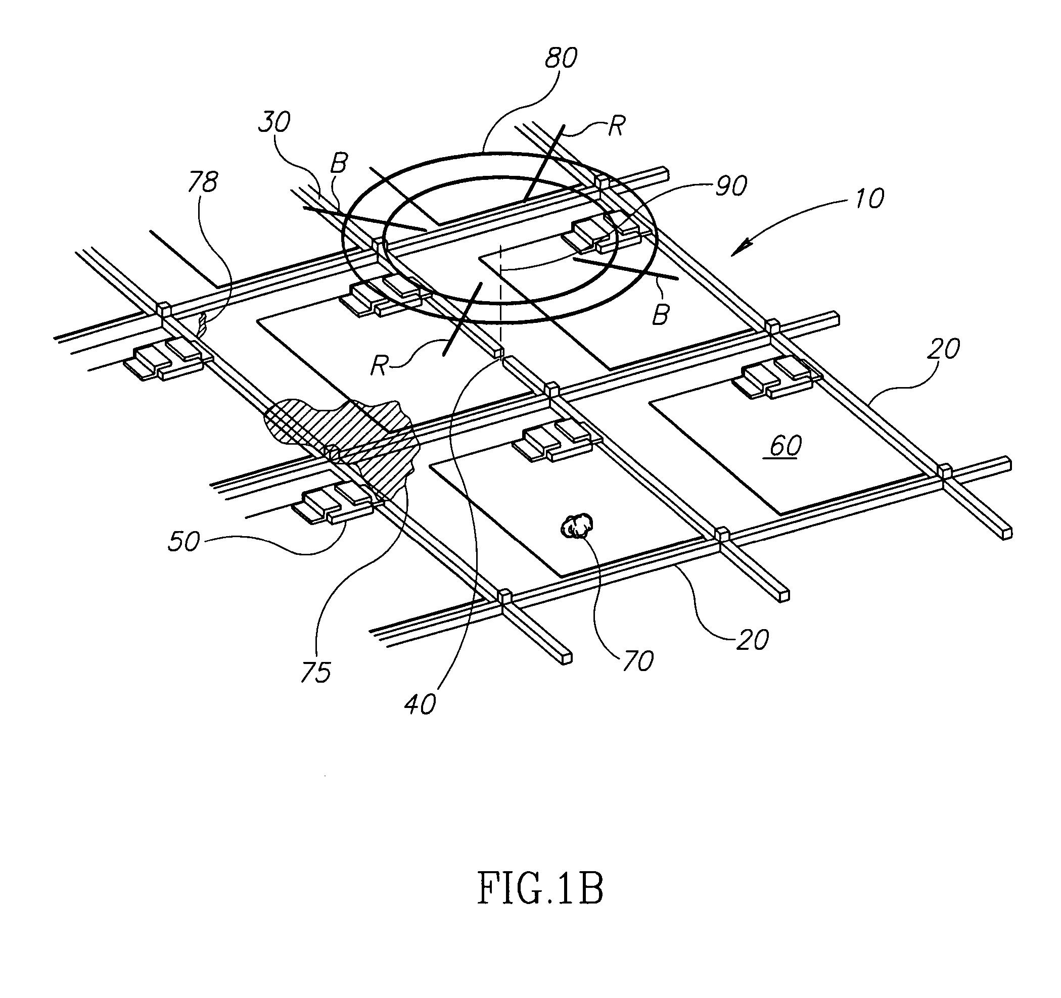
[0054]FIG. 1A is a simplified pictorial illustration of a portion of a display panel 10 including a plurality of elongate elements 20, such as electrical conductors, one of which 30 has a cut defect at defect location 40, and also includes transistors 50, electrodes 60, and other electrical components. Other defects that may appear on a display panel 10 include foreign particles 70, such as dust, which may be found on an outer surface of panel 10 or buried beneath a coating such as a photo resist (not seen), chemical residues 75, and shorts 78 forming an undesired electrical connection between two conductors 20. The display panel 10 requires inspection at defect location 40, for example in order to classify the type of defect thereat, for example as a cut, particle, short or other class of defect. The presence of a candidate defect location may be determined by initial automated inspection, for example using SuperVision™ or InVision™ automated optical inspection equipment commercial...


PUM

PropertyMeasurementUnit
angleaaaaaaaaaa
angleaaaaaaaaaa
angleaaaaaaaaaa

Abstract

An inspection system operative to inspect patterned devices having microscopic conductors, the system comprising a camera viewing a location of a candidate defect on a patterned substrate and acquiring thereat at least one image of the location, the camera defining an optical axis, the at least one image being illuminated by at least one illumination offset from the optical axis, the illumination being supplied along at least first and second axes of illumination that are mutually non-parallel in a plane corresponding to a plane of the patterned substrate, wherein a response to the illumination supplied along the first axis is differentiable from a response to the illumination supplied along the second axis and a defect classifier operative to receive the at least one image and to distinguish therewithin a candidate defect caused by a cut or a candidate defect caused by excess material, from one another and / or from other types of candidate defects.

Description

FIELD OF THE INVENTION[0001]The present invention relates generally to inspection of microscopic features on manufactured objects.BACKGROUND OF THE INVENTION[0002]Automated Optical Inspection systems for inspecting in-fabrication flat panel displays for defects, including SuperVision™ and InVision™ systems commercially available from Orbotech Ltd. of Yavne, Israel typically include defect classification sub-systems operative to acquire images of suspected defects that are illuminated using polychromatic or monochromatic bright field illumination.[0003]Some automated optical inspection systems for inspecting in-fabrication flat panel displays for defects, for example the Pointer-5000 series of optical testers, also commercially available from Orbotech Ltd, Yavne, Israel, additionally acquire images illuminated with generally monochromatic illumination supplied from locations that are offset from an optical axis.[0004]U.S. Pat. No. 6,947,151 describes a surface state inspecting method...

Claims


Application Information

Patent Timeline
Patent Type & Authority Patents(United States)
IPC IPC(8): G01N21/00
CPCG01N21/956B22C9/082
Inventor BEN-TULILA, RAPHAELBERLADSKY, EMILLEIZERSON, ILYASAPHIER, OFER
Owner ORBOTECH LTD
Why Eureka
Try Eureka