Ureteral stent with conforming retention structure

a ureteral stent and conforming technology, applied in the field of medical devices, can solve problems such as patient discomfort and discomfort for patients

Active Publication Date: 2008-07-08
BOSTON SCI SCIMED INC
View PDF123 Cites 37 Cited by
  • Summary
  • Abstract
  • Description
  • Claims
  • Application Information

AI Technical Summary

Benefits of technology

[0005]A ureteral stent includes an elongate member defining an axis and having a proximal end portion and a distal end portion. A first extension member and a second extension member extend from the proximal end portion of the elongate member. The first extension member and the second extension member each include a first portion, a second portion, a third portion and an end portion. In an unconstrained configuration, the first portion is arcuate and extends away from the axis defined by the elongate member, the second portion extends from the first portion in a distal direction, and the third portion extends from the second portion in a direction away from the axis defined by the elongate member. In the unconstrained configuration, the end portion of the first extension member and the end portion of the second extension member are spaced apart from each other sufficiently, and the first extension member and the second extension member are sufficiently rigid, to collectively help retain at least a portion of the ureteral stent within a bladder of a patient.

Problems solved by technology

Known ureteral stents often cause discomfort to the patient once the ureteral stents are positioned within the body due to the size and mass of the retention members.
The large mass of the curled retention structure does not easily conform to the bladder when the bladder is emptied or collapsed, resulting in patient discomfort.
Further discomfort can also result when the ureteral stent is removed from a patient due to the configuration of the retention member.

Method used


Image

  • Ureteral stent with conforming retention structure
  • Ureteral stent with conforming retention structure
  • Ureteral stent with conforming retention structure

Examples


Embodiment Construction

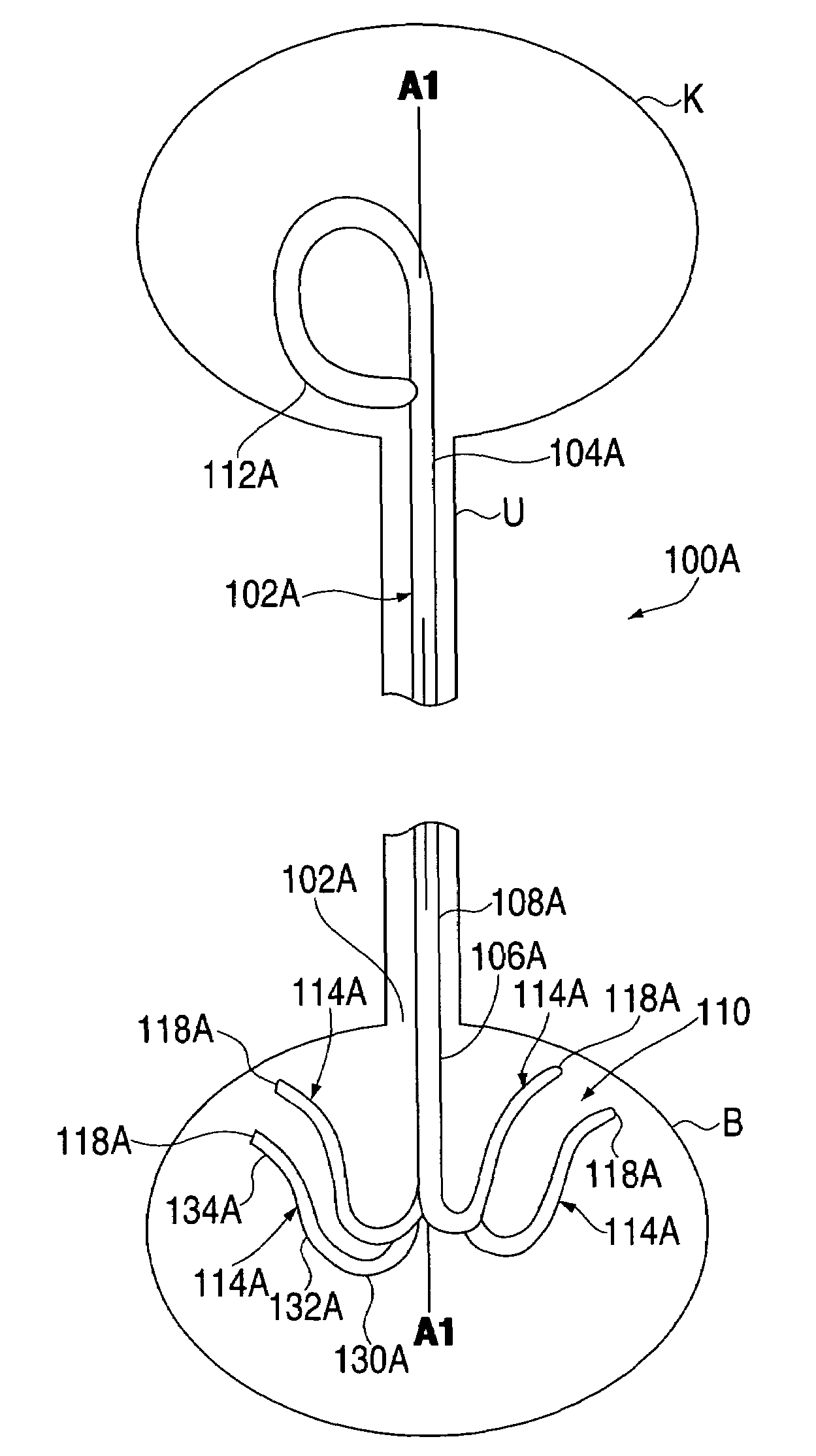
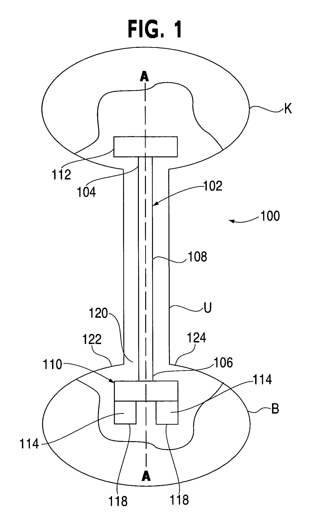
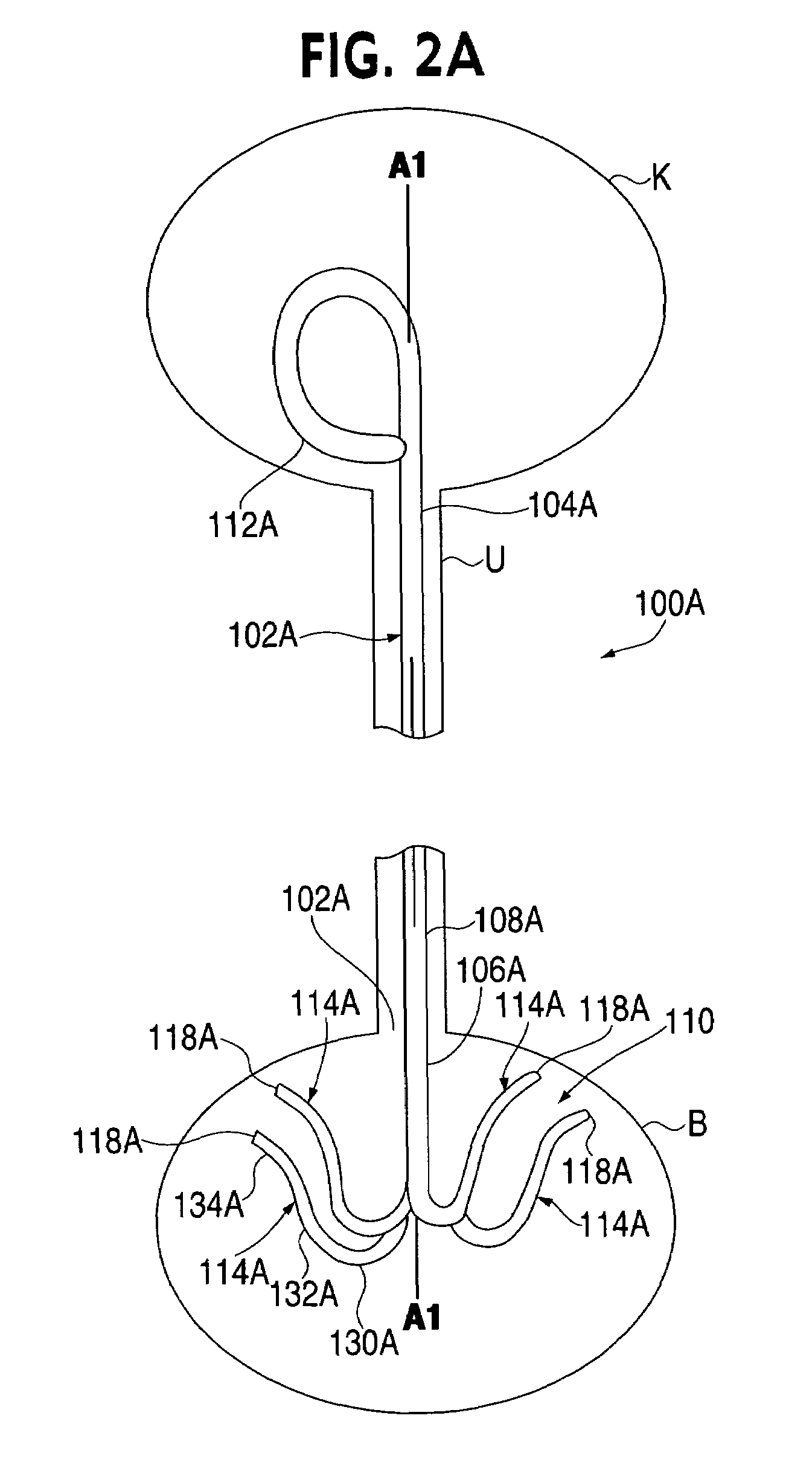
[0027]FIG. 1 is a schematic illustration of a ureteral stent 100 disposed within a urinary tract of a patient. Specifically, the ureteral stent 100 is placed or otherwise implanted into the urinary tract of a patient such that the ureteral stent 100 extends through the ureter U, from the kidney K of the patient to the bladder B of the patient. The ureteral stent 100 is configured to help facilitate the movement of fluid within a urinary tract of a patient.

[0028]The ureteral stent 100 includes an elongate member 102 having a distal end portion 104, a proximal end portion 106, and a medial portion 108. A retention portion 110 extends from the proximal end portion 106 of the elongate member 102. Similarly, a retention portion 112 extends from the distal end portion 104 of the elongate member 102. The elongate member 102 defines an axis A and a lumen (not shown in FIG. 1). The lumen may extend from the distal end portion 104 to the proximal end portion 106 of the elongate member 102. Th...


PUM


Abstract

A ureteral stent includes an elongate member defining an axis and having a proximal end portion and a distal end portion. A first extension member and a second extension member extend from the proximal end portion and each include a first portion, a second portion, a third portion and an end portion. In an unconstrained configuration, the first portion is arcuate and extends away from the axis, the second portion extends from the first portion in a distal direction, and the third portion extends from the second portion in a direction away from the axis. In the unconstrained configuration, the end portions of the first and second extension members are spaced apart from each other sufficiently, and the first extension member and the second extension member are sufficiently rigid, to collectively help retain at least a portion of the ureteral stent within a bladder of a patient.

Description

BACKGROUND[0001]The disclosed invention relates generally to a medical device and more particularly to a ureteral stent having a conforming retention structure to provide improved patient comfort.[0002]Known ureteral stents are typically placed within a urinary tract of a patient such that one end portion of the ureteral stent is located in either a kidney or a ureter of the patient and another end portion of the ureteral stent is located in a bladder of the patient. Some known ureteral stents include retention members configured to help retain the ureteral stent in position within the patient. Known ureteral stents are typically positioned within the urinary tract of the patient by placing a guidewire within the patient, sliding the ureteral stent on the guidewire, and then forcing the ureteral stent along the guidewire into a desired position within the patient using a push cannula. Such ureteral stents are often removed from the patient by pulling the ureteral stent from the urin...

Claims


Application Information

Patent Timeline
Patent Type & Authority Patents(United States)
IPC IPC(8): A61F2/04
CPCA61M27/008
Inventor WARD, TIM
Owner BOSTON SCI SCIMED INC
Why Eureka
Try Eureka