Fast-disabled voltage regulator circuit with low-noise feedback loop and operating method thereof

a voltage regulator circuit and feedback loop technology, applied in the direction of electric variable regulation, process and machine control, instruments, etc., can solve the problems of slow disassembly of voltage regulator circuit b>10/b>, inability to provide precise and stable output voltage, and inability to provide high dc voltage to the output node nout. the effect of a quick disassembly and output voltage and quick disassembly

Active Publication Date: 2008-07-08
XUESHAN TECH INC
View PDF8 Cites 10 Cited by
  • Summary
  • Abstract
  • Description
  • Claims
  • Application Information

AI Technical Summary

Benefits of technology

[0009]According to the present invention, the claimed voltage regulator circuit can quickly disable and pull down the feedback voltage of the amplifier circuit. At least two differently sized discharge transistors are added to the prior art voltage regulator circuit to quickly discharge the output voltage of the voltage regulator circuit through the discharge transistor. In addition, at least one bypass capacitor is added to the related feedback input terminal of the amplifier circuit. When filtering out the RF interference signal to reduce noise, the bypass capacitor utilizes the discharge transistor to fast pull down the feedback voltage of the amplifier circuit. It comes to lower the noise and reduce the discharge time. Therefore, the claimed voltage regulator circuit can quickly disable and provide a low-noise, precise, and stable output voltage.
[0012]The claimed low-noise voltage regulator circuit is based on the structure of the prior art voltage regulator circuit. At least two discharge transistors and a bypass capacitor are added for quickly pulling down the feedback voltage of the amplifier circuit and for quickly discharging the output voltage of the voltage regulator through the discharge transistors. It has a low-noise feedback pull-low mechanism and an ability of fast disabling the operation. In addition, it can further lower the noise and reduce the discharge time and unnecessary power consumption. To sum up, it makes the voltage regulator circuit able to provide a low-noise, precise, and stable output voltage.

Problems solved by technology

It means that the first voltage source VCC no longer provides a high DC voltage to the output node NOUT.
However, the loading capacitor CL leads to a finite duration of the discharging time, which implies that the voltage regulator circuit 10 is not only disabled slowly but also not able to provide a precise and stable output voltage.
Moreover, the increase of the discharging time implies an increase in power consumption as well as the inability to disable the output voltage precisely and promptly.

Method used


Image

  • Fast-disabled voltage regulator circuit with low-noise feedback loop and operating method thereof
  • Fast-disabled voltage regulator circuit with low-noise feedback loop and operating method thereof
  • Fast-disabled voltage regulator circuit with low-noise feedback loop and operating method thereof

Examples


Embodiment Construction

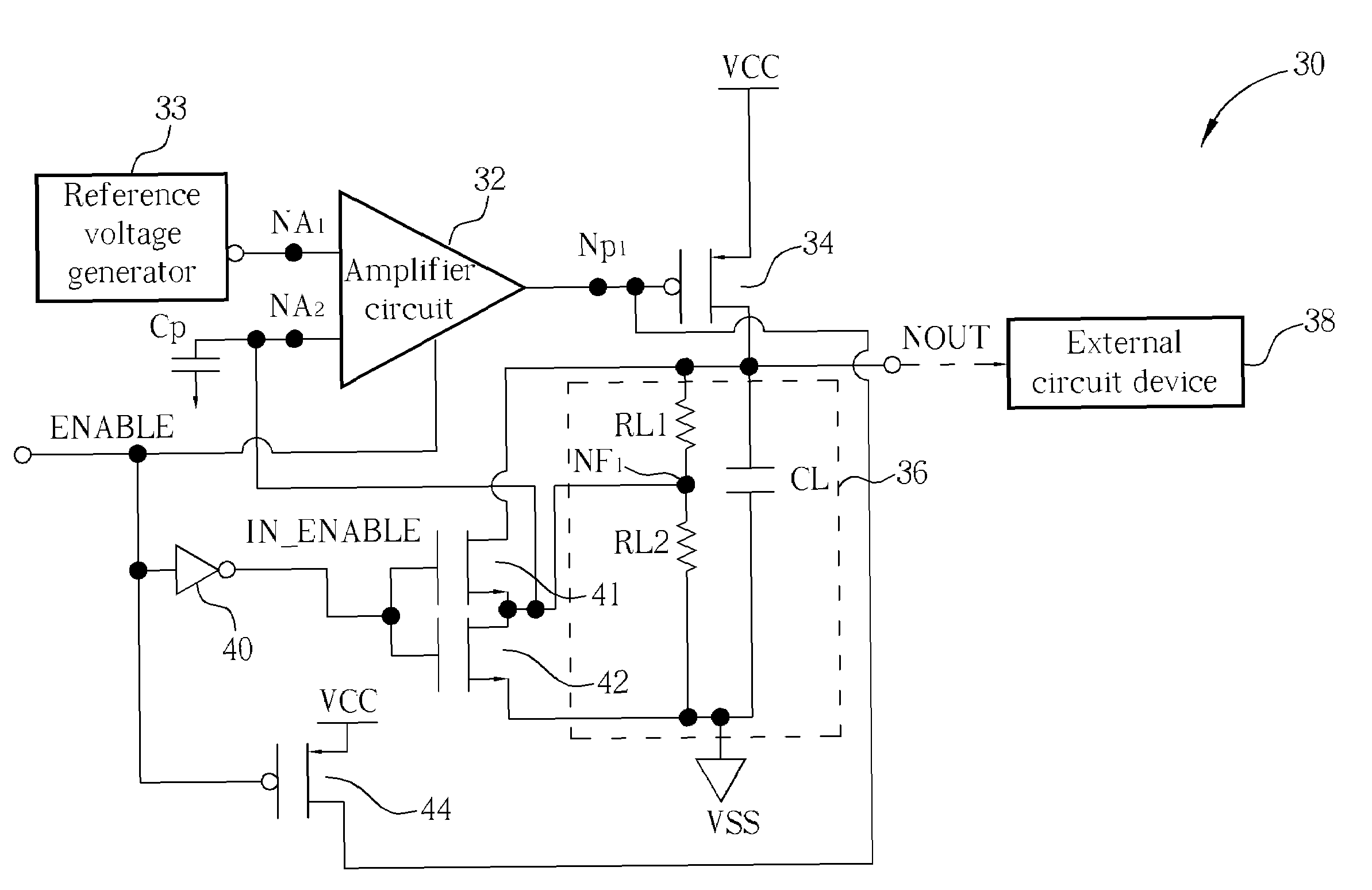
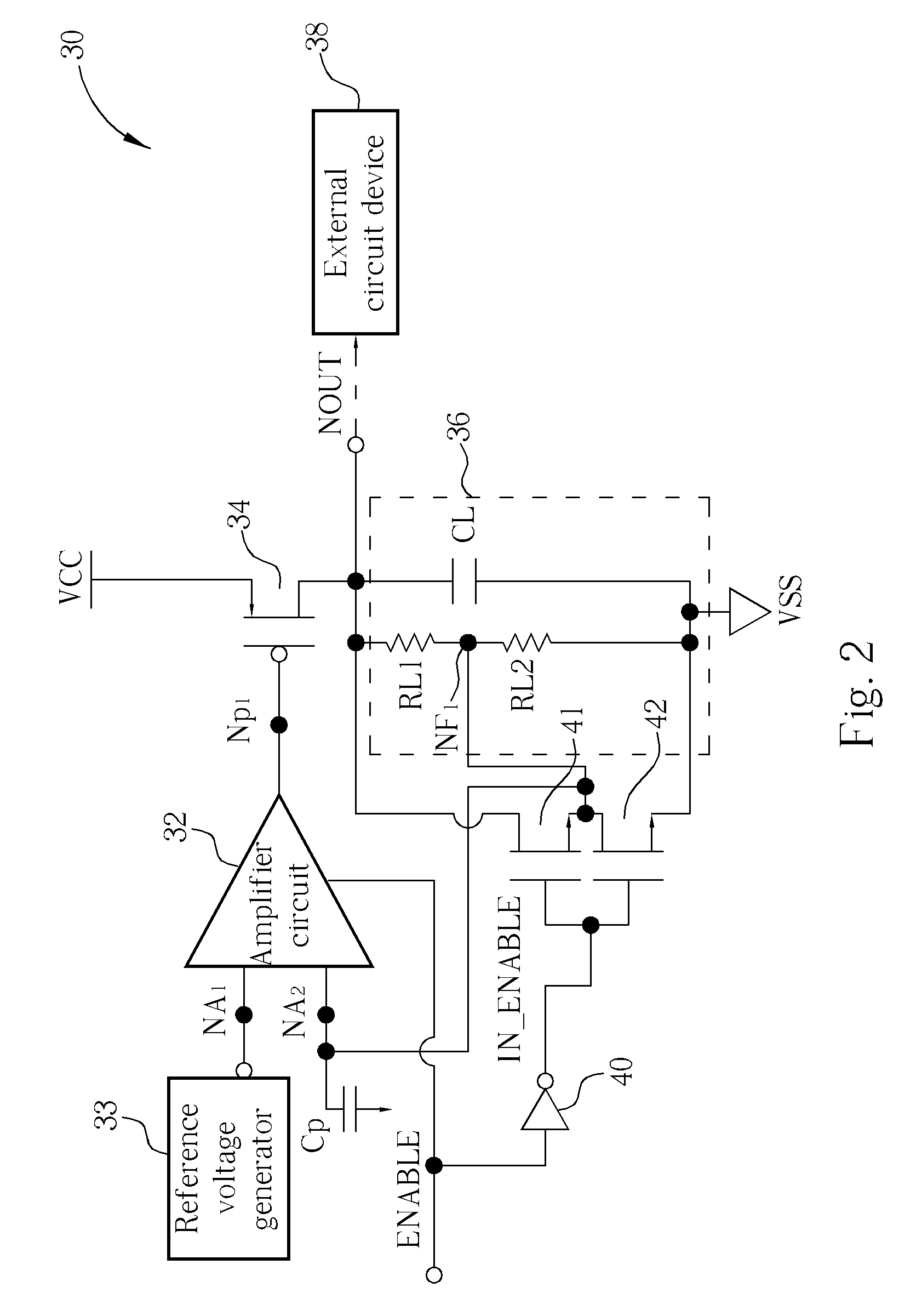
[0019]Technical characteristics of the present invention emphasizes on the operation when a low-noise voltage regulator circuit is disabled. Please refer to FIG. 2. FIG. 2 is a diagram of an embodiment of a low-noise voltage regulator circuit 30 according to the present invention. Please note that the voltage regulator circuit 30 shown in FIG. 2 is built by several MOS transistors and related circuit components. In practical implementation, other transistors, such as BJTs, can also be used to replace MOS transistors. Please refer to FIG. 2, the voltage regulator circuit 30 comprises an amplifier circuit 32, an output transistor 34, an inverter 40, a first discharge transistor 41, a second discharge transistor 42, and a loading module 36. In practical implementation, the amplifier circuit 32 can be an operational amplifier or a differential amplifier. The amplifier circuit 32 comprises an output terminal Np1, a first receiving terminal NA1, and a second receiving terminal NA2. The fi...


PUM


Abstract

A low-noise voltage regulator circuit with quick disablement includes an amplifier for outputting a driving voltage according to a reference voltage, a feedback voltage on a feedback node, and an enable signal; an output transistor coupled among the amplifier, an output node, and a first voltage source for outputting an output voltage at the output node; a first discharge transistor having a first size and coupled among the enable signal, the output node, and the feedback node; and a second discharge transistor having a second size being different than the first size and coupled among the enable signal, the feedback node, and a second voltage source; wherein when the enable signal disables the amplifier, the enable signal turns on the first discharge transistor and the second discharge transistor such that the output voltage is quickly pulled down to close a level provided by the second voltage source.

Description

CROSS REFERENCE TO RELATED APPLICATIONS[0001]This is a continuation-in-part of U.S. application Ser. No. 10 / 711,618 entitled, “Fast-Disabled Voltage Regulator Circuit with Low-Noise Feedback Loop and Operating Method Thereof”, which was filed on Sep. 29, 2004 and is included herein by reference.BACKGROUND[0002]The present invention provides a low-noise voltage regulator circuit and an operating method thereof for quickly disabling the voltage regulator circuit, and more particularly, to a low-noise voltage regulator circuit and an operating method thereof that utilize an enable signal for connecting an output node, through a feedback node, to a ground voltage source so as to quickly pull down the output voltage of the low-noise voltage regulator circuit.[0003]In all kinds of electrical products on the market, a voltage regulator circuit is often used to execute the work of voltage regulation and to provide a stable voltage to other circuit modules in the electrical product. For exam...

Claims


Application Information

Patent Timeline
Patent Type & Authority Patents(United States)
IPC IPC(8): G05F1/575G05F1/40
CPCG05F1/575
Inventor KE, LING-WEICHIU, CHI-KUN
Owner XUESHAN TECH INC
Why Eureka
Try Eureka