
Generation of hue slice table for gamut mapping

a technology of gamut mapping and hue slice, which is applied in the direction of digitally marking record carriers, color signal processing circuits, instruments, etc., can solve the problems of ignoring other chroma points of interest (e.g. surface) within the segment, and the foregoing technique suffers from some problems, so as to achieve accurate representation of the gamut boundary

Inactive Publication Date: 2008-07-08
CANON KK
View PDF15 Cites 22 Cited by
  • Summary
  • Abstract
  • Description
  • Claims
  • Application Information

AI Technical Summary

Benefits of technology

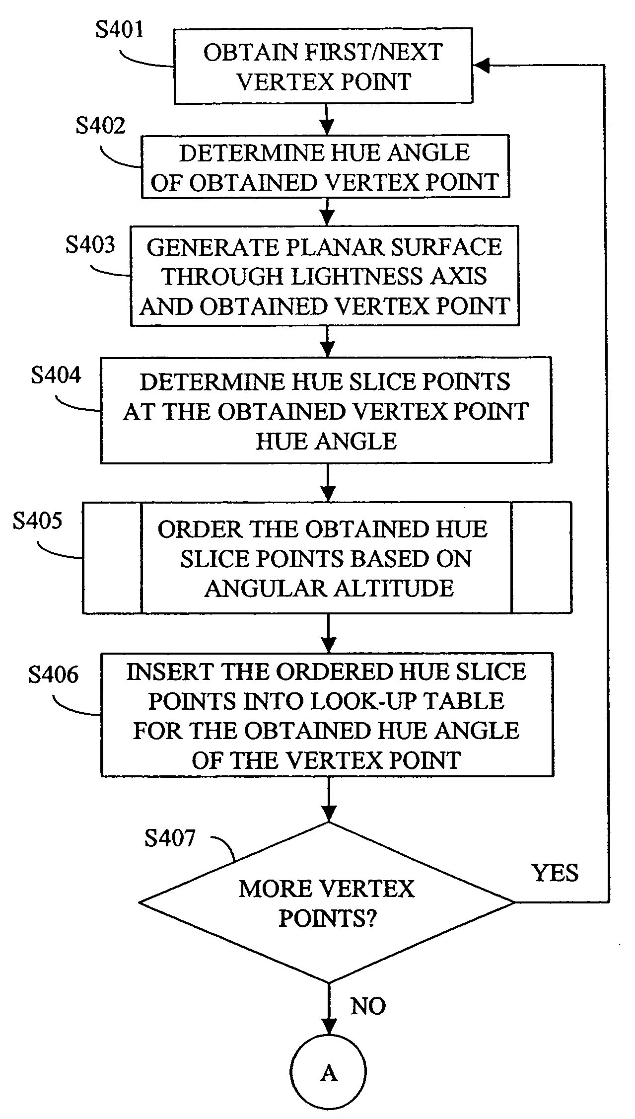
[0016]As a result of the foregoing process, the hue slice table is variable in size and variable in the number of elements, depending on the number of vertex point hue slices and the number of additional hue slices needed to populate the table such that adjoining slices fall within a desired hue angle threshold. As such, each maximum chroma point along the gamut boundary surface, as well as other vertex points of interest will have a hue slice in the table, thereby forming a more accurate representation of the gamut boundary.

Problems solved by technology

The foregoing technique does, however, suffer from some problems.
One problem is that, since only a maximum chroma point is obtained for each segment, other chroma points of interest (e.g., other chroma points on the boundary surface) within the segment can be missed.
Thus, when it is necessary to use interpolation to map a point that falls between hue slices in the table, the interpolated result may not be a very accurate representation of the boundary surface.
As a result, sorting the hue slice points by lightness values would result in an erroneous representation of the gamut boundary since the darkest point would be out of order relative to the darkest point on the lightness axis.

Method used


Image

  • Generation of hue slice table for gamut mapping
  • Generation of hue slice table for gamut mapping
  • Generation of hue slice table for gamut mapping

Examples


Embodiment Construction

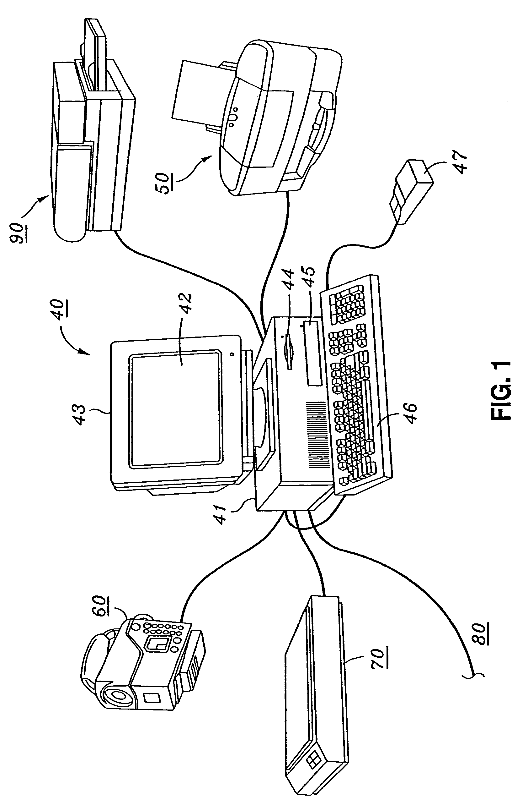
[0037]FIG. 1 depicts an example of a computing environment in which the present invention may be implemented. Computing equipment 40 includes host processor 41 which comprises a personal computer (hereinafter “PC”), preferably an IBM PC-compatible computer having a windowing environment such as Microsoft Windows 98, Windows 2000, Windows Me, Windows XP, or Windows NT, or other windowing system such as LINUX. Alternatively, host processor 41 may be an Apple computer or other non-windows based computer. Computing equipment 40 preferably includes color monitor 43 having a display screen 42, keyboard 46 for entering data and user commands, and pointing device 47, which preferably comprises a mouse for pointing to and for manipulating objects displayed on display screen 42.

[0038]Computing equipment 40 preferably also includes a computer-readable memory media such as fixed disk 45 and / or floppy disk drive 44. Floppy disk drive 44 provides a means whereby computing equipment 40 can access ...


PUM

PropertyMeasurementUnit
hue angleaaaaaaaaaa
threshold angleaaaaaaaaaa

Abstract

A table representing a color gamut for a device for use in a color management system where colors are represented in a color appearance space comprises data representing a collection of hue slices through a boundary surface of the color gamut. The collection of hue slices comprises entries for vertex point hue slices obtained at each vertex point on the boundary surface of the color gamut, and entries obtained for additional hue slices between adjoining vertex point hue slices, where a number of the additional hue slices is determined such that there is no more than a specified angular difference between each hue slice. Each hue slice is represented by a hue value and a collection of hue slice points each containing a lightness value and a chroma value. The hue slice points of each hue slice are ordered in the table based on an angular altitude of each point, the angular altitude of each point being determined between a lightness axis of the color gamut and a vector projected from a midpoint of the lightness axis to the hue slice point.

Description

BACKGROUND OF THE INVENTION[0001]1. Field of the Invention[0002]The present invention generally relates to generation of a hue slice table for use in gamut mapping, and extraction of a hue slice from the generated table. In more detail, the present invention generates a hue slice table by obtaining hue slices at each vertex point on a boundary surface of a device's color gamut and then generating additional hue slices between the vertex point hue slices to fill-in the table. In generating each hue slice, the invention utilizes a point ordering technique that results in a more accurate representation of each slice. Once the table is generated, the invention provides a unique linear interpolation extraction technique to obtain a hue slice from the table if a hue slice at a requested hue angle does not already exist in the table.[0003]2. Description of the Related Art[0004]Gamut mapping relates to image reproduction from one imaging device to another, such as reproducing an image displ...

Claims


Application Information

Patent Timeline
Patent Type & Authority Patents(United States)
IPC IPC(8): G03F3/08
CPCH04N1/6058
Inventor SLOAN, ROCKLIN J.HAIKIN, JOHN S.
Owner CANON KK
Learn More