Compact PCI ejector latch

a technology of ejector latches and latches, which is applied in the direction of electrical apparatus, support structure mounting, casings/cabinets/drawers, etc., can solve the problems of relatively large amount of emf signal leakage (electromagnetic frequency radiation), low profile of pci board latches, and limited degree of movement and mechanical leverage, etc., to achieve a greater degree of rotation, reduce emf leakage, and facilitate mounting

Inactive Publication Date: 2008-07-08
SOUTHCO
View PDF39 Cites 61 Cited by
  • Summary
  • Abstract
  • Description
  • Claims
  • Application Information

AI Technical Summary

Benefits of technology

[0013]The objects of the present invention are realized in a low profile Compact PCI board latch, having a fold-down handle that operates with a greater degree of rotation, and has a separate alignment guide block, which facilitates its mounting to the board's faceplate and thereby requires a smaller faceplate aggregate cutout area thereby reducing EMF leakage and enhancing EMC compatibility.
[0016]The latch has a base that is mounted to the outside face of the compact PCI board's faceplate with its entire structure being outboard of the PCI board faceplate. A separate alignment guide block mounts to inside face of the faceplate to extend inwardly towards the chassis connectors. The latch, including its base and the separate alignment guide block are mounted to the faceplate with but two screws. The two-phase operation of the pawl permits the faceplate to extend further beyond the outside edge of the board than with solely rotational movement pawls. This increases the EMF shielding and enhances EMC levels for the latch and faceplate combination.
[0019]From the fully inserted configuration / position, the user first rotates the spring loaded catch which in turn releases the handle from the base and permits it to be rotated outwardly from the board's faceplate. As the handle is rotated though the first 75 degrees, it pivots around the end of a central slot in the base halves (juxtaposed base plates). Slots in the end of the handle contact pins on the pawl. The pawl rotates around a pin and ejects the faceplate / board structure from the chassis connector by moving the board outwardly above the chassis keeper flange. A further 15 degree rotation of the handle causes the handle to pivot around the end of semi-circular slots in the base halves (juxtaposed base plates). The first slots now drive the pawl pins down vertical portions of “L”-shaped slots in the base plates, causing the pawl to disengage from the chassis keeper flange with a longitudinal movement. The board is now free to be removed (pulled) from the chassis. The ends of the pins on the pawl have a tear-drop shape which prevents them from beginning the vertical travel before the extraction rotation is completed (the full 75 degrees of rotation).

Problems solved by technology

Furthermore, such prior art compact PCI board latches often do not have a low profile and generally have a limited degree of movement and mechanical leverage.
This prior art device has a high profile and its faceplate mounting with relatively large cutout results in a relatively large amount of EMF signal leakage (electromagnetic frequency radiation).

Method used


Image

  • Compact PCI ejector latch
  • Compact PCI ejector latch
  • Compact PCI ejector latch

Examples


Embodiment Construction

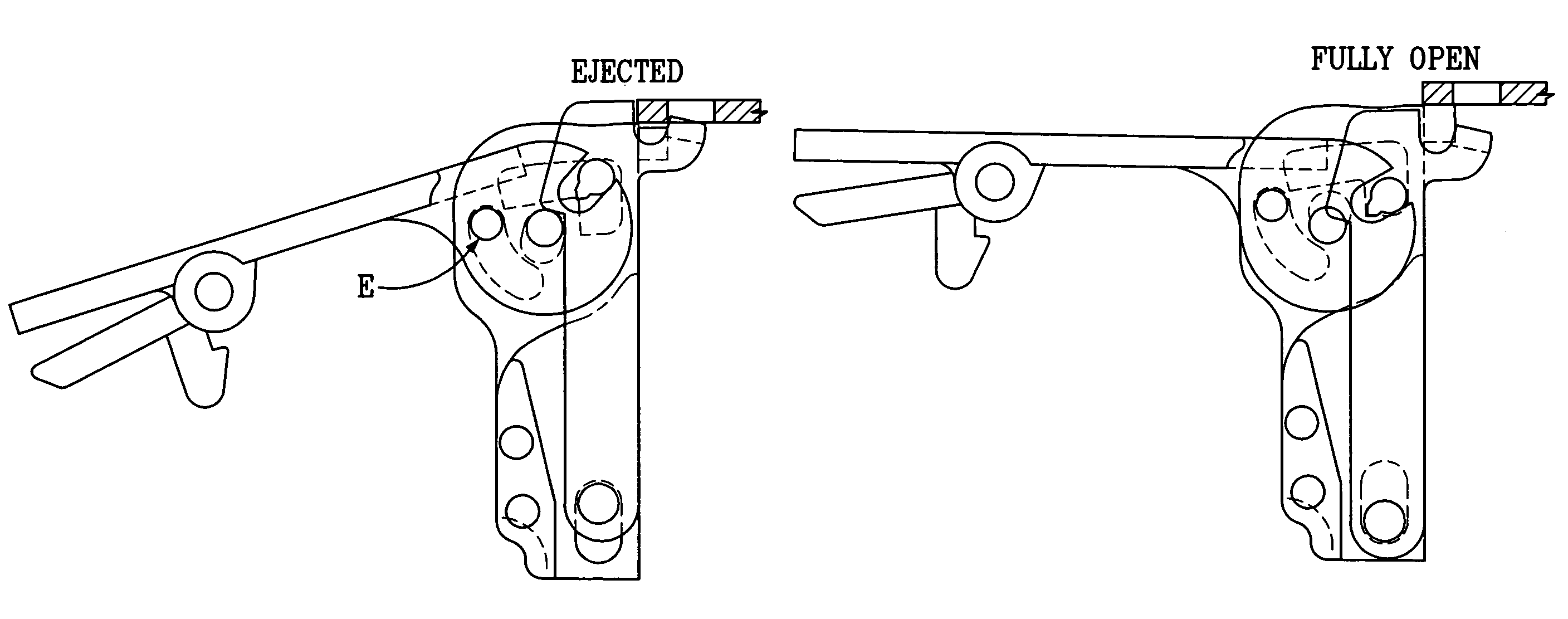
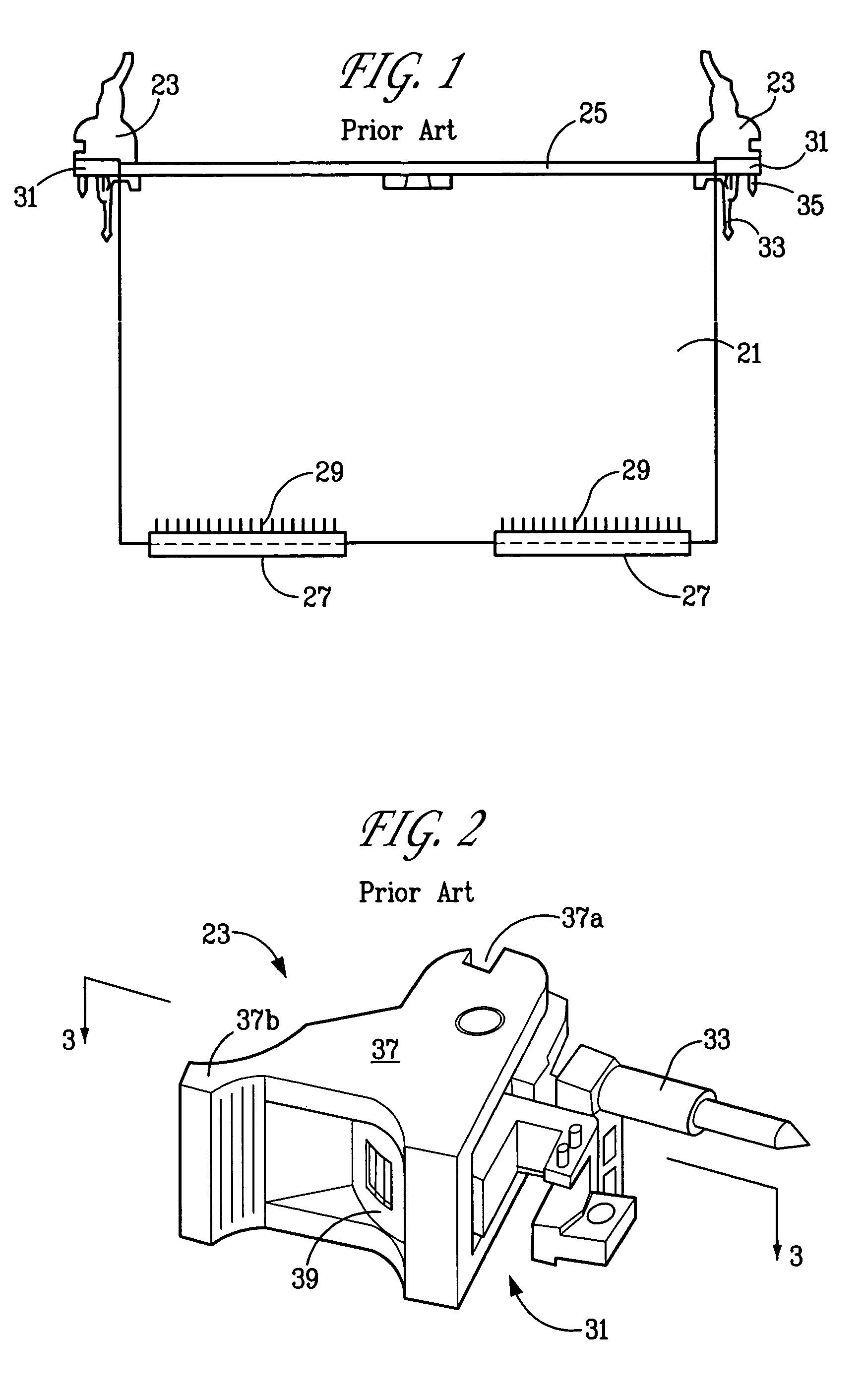
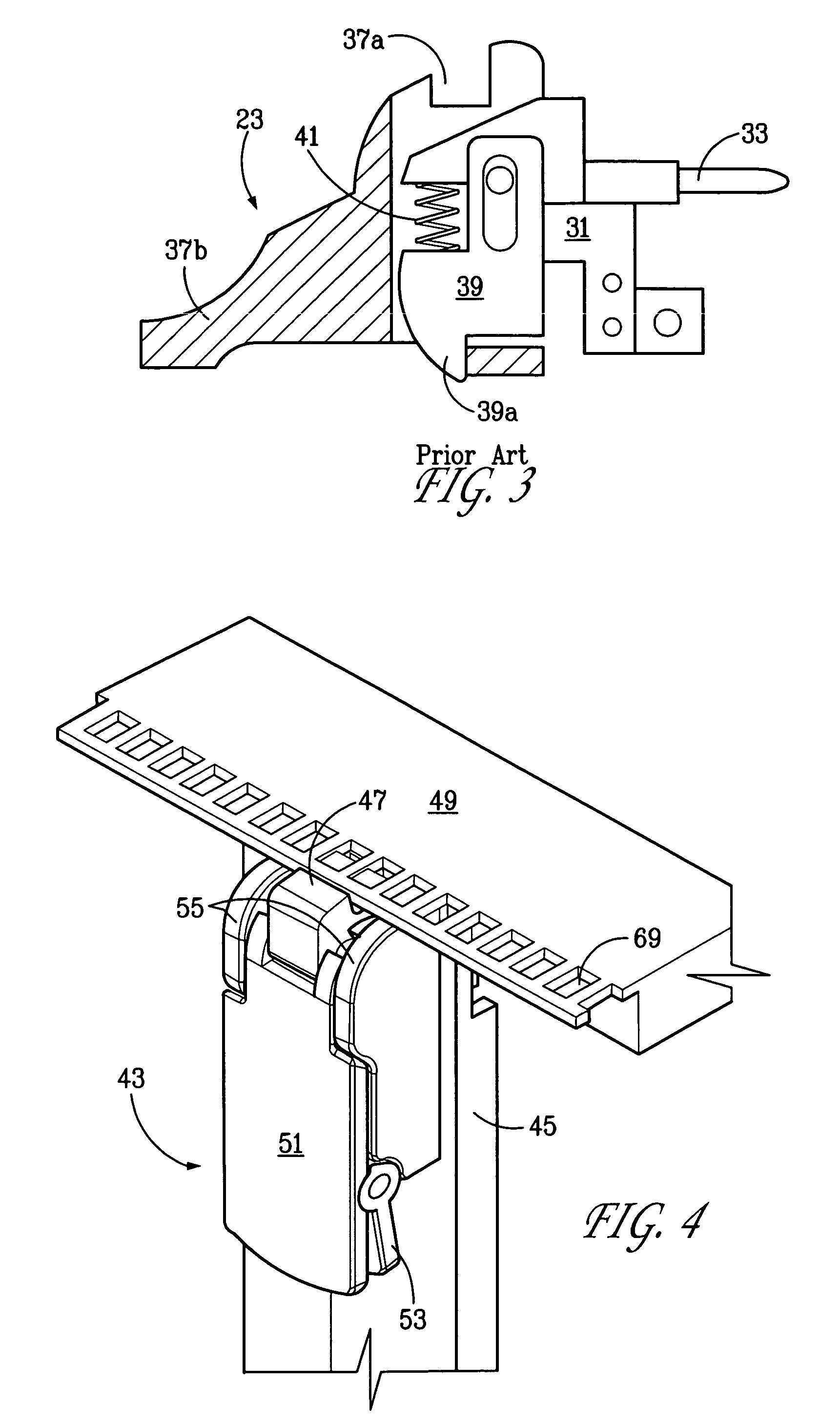
[0044]The present invention is fold-down low profile inject / eject latch which meets IEEE standards for compact peripheral interconnection (PCI) boards. Such compact PCI boards have been standardized to have aluminum faceplates at their outermost edges. These faceplates primarily provide EMF shielding. The operation of this latch permits a construction / structure which yields enhanced EMC (electromagnetic compatibility) by permitting increased shielding and reduced EMF emissions past an IEEE standards PCI board faceplate. The design and operation of the present latch invention permits a reduction in the cumulative openings and the aggregate area of the openings through the board's faceplate, including the addition of lateral extensions to the faceplate outboard its side edges, which lateral extensions are a part of and within the scope of the present invention.

[0045]The invention creates a motion control of the pawl and handle that is created by separately and sequentially pivoting ab...


PUM


Abstract

A latch for a Compact PCI board, which incorporates inject and eject and engage and disengage functions, has a low profile shape, whereof a fold-down handle operates through a total arc of 90 degrees. Enhanced electromagnetic compatibility (EMC) is provided, by more efficient EMC shielding and by reduced electromagnetic force (EMF) radiation pass-through. The latch, in its inject / eject operation, undergoes a two-phase motion, which utilizes a rotary motion to insert / extract the board from electrical connection, and utilizes a linear motion to engage / disengage the latch pawl from the chassis (keeper). A separate alignment pin block, normally carrying a lead guide pin and a seating guide pin, is independent of the structure for the base of the latch. This permits the alignment pin block to be mounted to the inside of the faceplate and the latch to be mounted to the outside of the faceplate. By so doing, the cumulative (aggregate) area of the opening(s) through the faceplate is reduced, which thereby increases the EMC (electromagnetic compatibility) of the design by reducing EMF radiation pass-through.

Description

RELATED APPLICATIONS[0001]Applicant claims the benefit under 35 United States Code 119(e) of U.S. Provisional Application Ser. No. 60 / 477,274, filed Jun. 9, 2003 on the present invention, and incorporates the disclosure thereof herein by reference.BACKGROUND OF THE INVENTION[0002]The present invention relates to latches and levers, specifically ejector latches and ejector levers which may be adapted for use to secure and release computer-type boards in racks and cabinets, such as large boards known as peripheral component interconnect (PCI) boards. These boards are used to hold such electronic components as processor circuits, banks of switches, banks of transducers, transformers and other components and modules. Such PCI boards are generally larger than PC boards (personal computer boards) and can be generally square or rectangular in shape; and are generally sized from six (6) inch to ten (10) inches on a side. Compared to the much larger boards, previously used in the computer, t...

Claims


Application Information

Patent Timeline
Patent Type & Authority Patents(United States)
IPC IPC(8): H05K7/14H05K7/18
CPCH05K7/1409
Inventor SCHLACK, RICHARD E.
Owner SOUTHCO
Why Eureka
Try Eureka