Cyclone dust collecting device for use in a vacuum cleaner

a technology of dust collection device and vacuum cleaner, which is applied in the direction of auxillary pretreatment, cleaning filter means, separation processes, etc., can solve the problems of uneven air flow in the cyclone dust collection device as a whole, and achieve the effect of smooth air flow

Inactive Publication Date: 2008-07-15
DAEWOO ELECTRONICS CO LTD
View PDF19 Cites 22 Cited by
  • Summary
  • Abstract
  • Description
  • Claims
  • Application Information

AI Technical Summary

Benefits of technology

[0006]It is, therefore, an object of the present invention to provide a cyclone dust collecting device capable of preventing dust accumulated in a dust collection chamber from flowing back into a cyclonic air flow chamber and making air to flow more smoothly.

Problems solved by technology

Further, the air flow in the cyclone dust collecting device is not smooth as a whole since there is no discharge passageway for the air introduced into the dust collection chamber 930.

Method used


Image

  • Cyclone dust collecting device for use in a vacuum cleaner
  • Cyclone dust collecting device for use in a vacuum cleaner
  • Cyclone dust collecting device for use in a vacuum cleaner

Examples


Embodiment Construction

[0022]Hereinafter, a preferred embodiment of the present invention will be described with reference to the accompanying drawings.

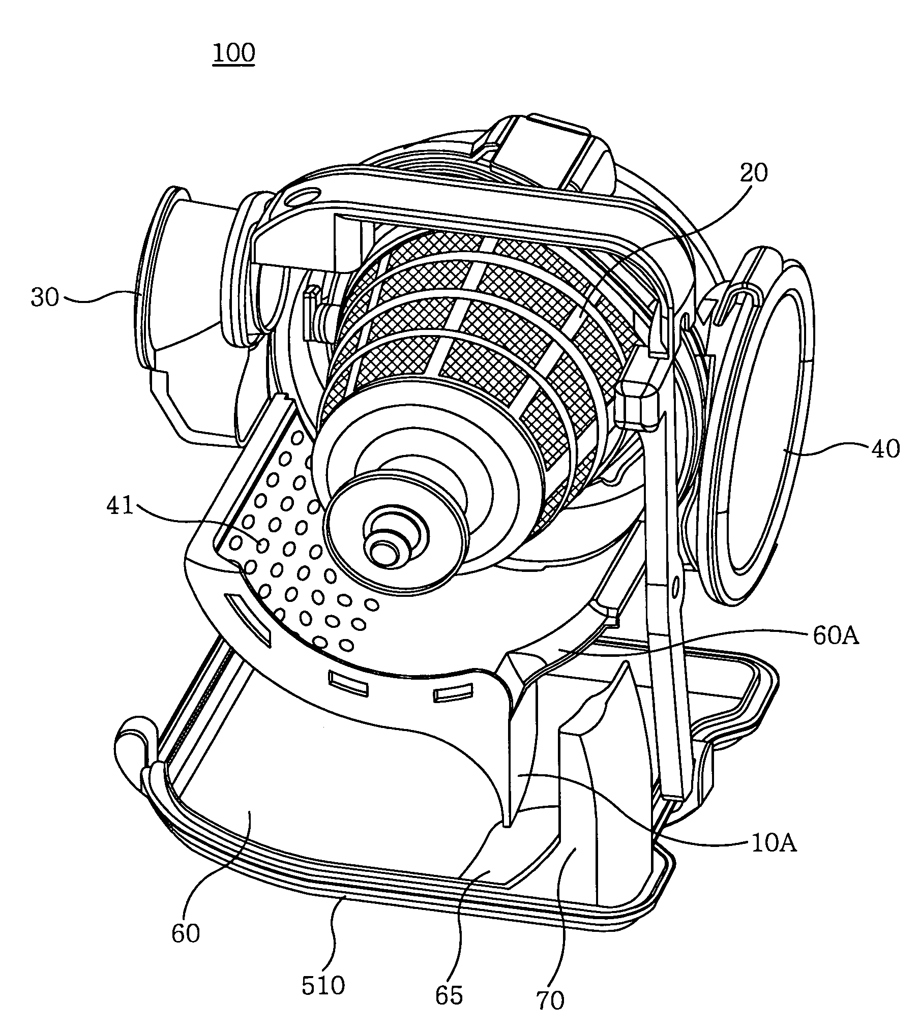
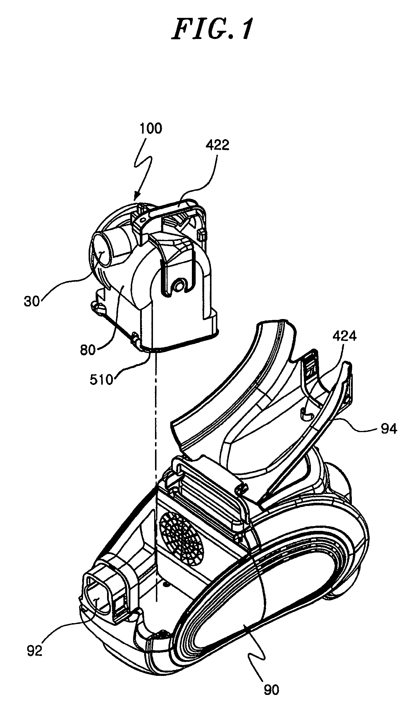
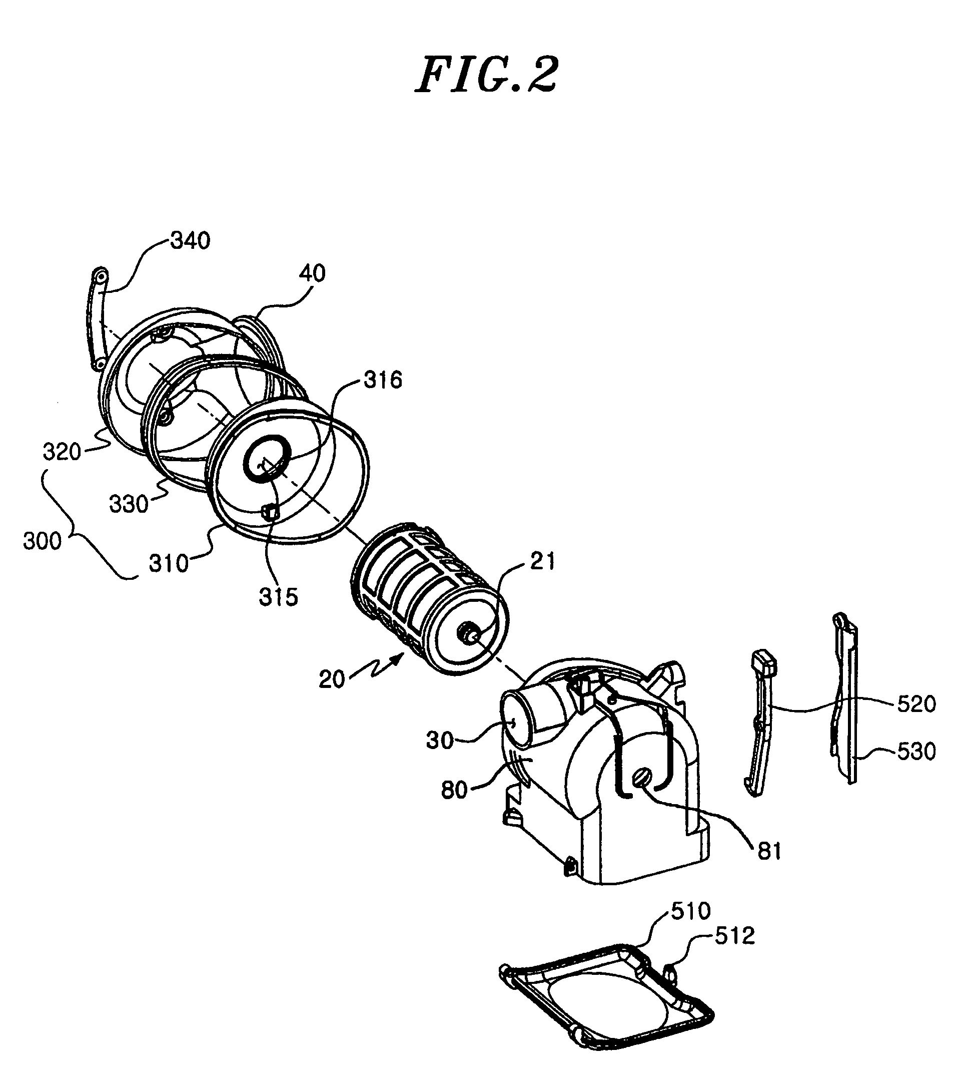
[0023]FIG. 1 is a perspective view of a vacuum cleaner with a cyclone dust collecting device 100 separated from a main body of the vacuum cleaner and FIG. 2 is an exploded perspective view of the cyclone dust collecting device 100 of the present invention. Further, FIG. 3 is a perspective view of the cyclone dust collecting device 100 of the present invention with a housing 80 removed and FIG. 4 is a schematic cross sectional view showing an air flow in the cyclone dust collecting device 100.

[0024]As shown in FIGS. 1 to 4, the cyclone dust collecting device 100 includes the housing 80 defining an approximately cylindrical inner space (cyclonic air flow chamber) 50 and a suction port 30 and a discharge port 40 are disposed in the front side and in the rear side of the housing 80, respectively. The suction port 30 and the discharge port 40 are preferably dis...


PUM

PropertyMeasurementUnit
curved shapeaaaaaaaaaa
massaaaaaaaaaa
timeaaaaaaaaaa

Abstract

A cyclone dust collecting device, for use in a vacuum cleaner, includes a housing defining therein a cyclonic air flow chamber. A dust collection chamber is disposed under the cyclonic air flow chamber and a partition wall is disposed between the cyclonic air flow chamber and the dust collection chamber. An opening and at least one ventilation hole are provided in opposite sides of the partition wall, respectively, so that a part of air and dust vortically moving in the cyclonic air flow chamber are introduced into the dust collection chamber through the opening and the air in the dust collection chamber flows back into the cyclonic air flow chamber through the ventilation hole.

Description

FIELD OF THE INVENTION[0001]The present invention relates to a cyclone dust collecting device for use in a vacuum cleaner; and, more particularly, a cyclone dust collecting device capable of preventing dust from flowing back from a dust collection chamber to a cyclonic air flow chamber and making an air flow therein more smooth.BACKGROUND OF THE INVENTION[0002]In a conventional vacuum cleaner of a dust bag type, suctioned dust is accumulated in the dust bag made of a disposable paper. When the dust bag is filled with dust, the dust bag should be changed. Recently, there has been developed a so-called cyclone type dust collecting device in which suctioned air is spirally rotated to separate dust or the like having a relatively greater mass from the air by a centrifugal force without employing a disposable dust bag.[0003]FIG. 6 shows a schematic cross sectional view of a conventional cyclone dust collecting device disclosed in U.S. Patent Laid-open Publication No. 2002 / 88078 A1.[0004]...

Claims


Application Information

Patent Timeline
Patent Type & Authority Patents(United States)
IPC IPC(8): A47L5/00A47L9/16
CPCA47L9/1683A47L9/1608
Inventor LEE, NAM HO
Owner DAEWOO ELECTRONICS CO LTD
Why Eureka
Try Eureka