Engine-driven work machine

a work machine and engine technology, applied in the direction of machines/engines, mechanical equipment, combustion air/fuel air treatment, etc., to achieve the effect of effectively cooling the exhaust muffler

Active Publication Date: 2008-07-15
HONDA MOTOR CO LTD
View PDF9 Cites 34 Cited by
  • Summary
  • Abstract
  • Description
  • Claims
  • Application Information

AI Technical Summary

Benefits of technology

[0009]Accordingly, it is an aspect of the present invention to provide an engine-driven work machine, wherein natural cooling of an exhaust muffler and an engine is effectively performed even after operation of the engine has stopped.
[0012]With the first feature of the present invention, when operation of the cooling fan is stopped following stoppage of operation of the engine, a convection flow is generated around the exhaust muffler due to a residual heat of the exhaust muffler. In this process, the ascending air flow is suppressed on the side of the exhaust muffler by the air guide plate covering the exhaust muffler and the duct member connecting the air guide plate, while the ascending air flow is generated on the other side face opposite the one side face. The ascending air flow attracts the air on the side of the air guide plate, so that the air in the cooling-air passage also flows around onto the other side face of the exhaust muffler to become the ascending air flow. The continuous process facilitates the natural cooling of the engine and the exhaust muffler.
[0015]With the second feature of the present invention, the exhaust muffler is protected by the muffler box. Moreover, the natural cooling of the engine and the exhaust muffler is effectively facilitated even after operation of the engine has stopped by ascending the air flow toward the air-discharge port. The ascending air flow is smoothly generated from the residual heat of the exhaust muffler in a space between the other side face of the exhaust muffler and an inner wall of the muffler box opposite the other side face.
[0016]The exhaust muffler and the air guide plate serve as sound-insulating walls cooperatively isolating the cooling-air passage in the duct member and the air-discharge port in the muffler box from each other, thereby effectively preventing leakage of the noise generated by the operation of the engine and other components through the air-discharge louver. The above-described structural arrangement contributes to an improvement in the silencing performance of the engine-driven work machine.
[0018]With the third feature of the present invention, the cooling air flowing out of the cooling-air passage is blown against a broader side face of the exhaust muffler to effectively cool the exhaust muffler.

Problems solved by technology

However, in the above-described engine-driven generator, heat from the engine and the exhaust muffler is liable to be confined within the duct member and the muffler box after stoppage of the operation of the engine, leading to a demand for facilitation of natural cooling of the engine and the exhaust muffler.

Method used


Image

  • Engine-driven work machine
  • Engine-driven work machine
  • Engine-driven work machine

Examples


Embodiment Construction

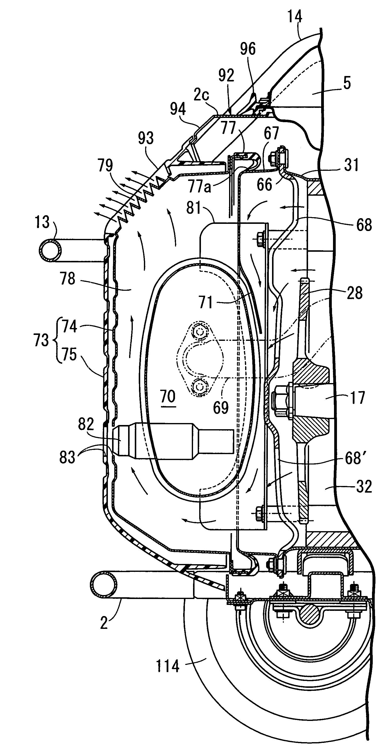
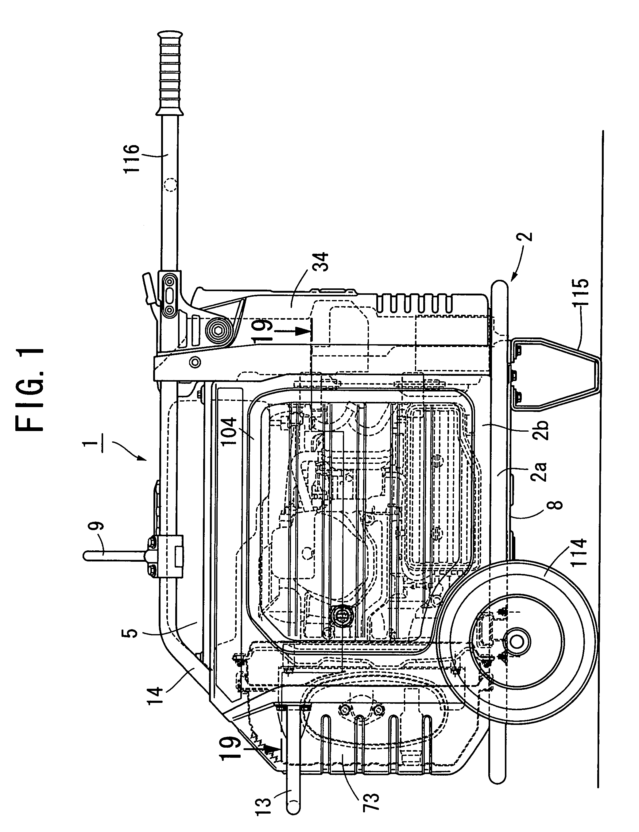
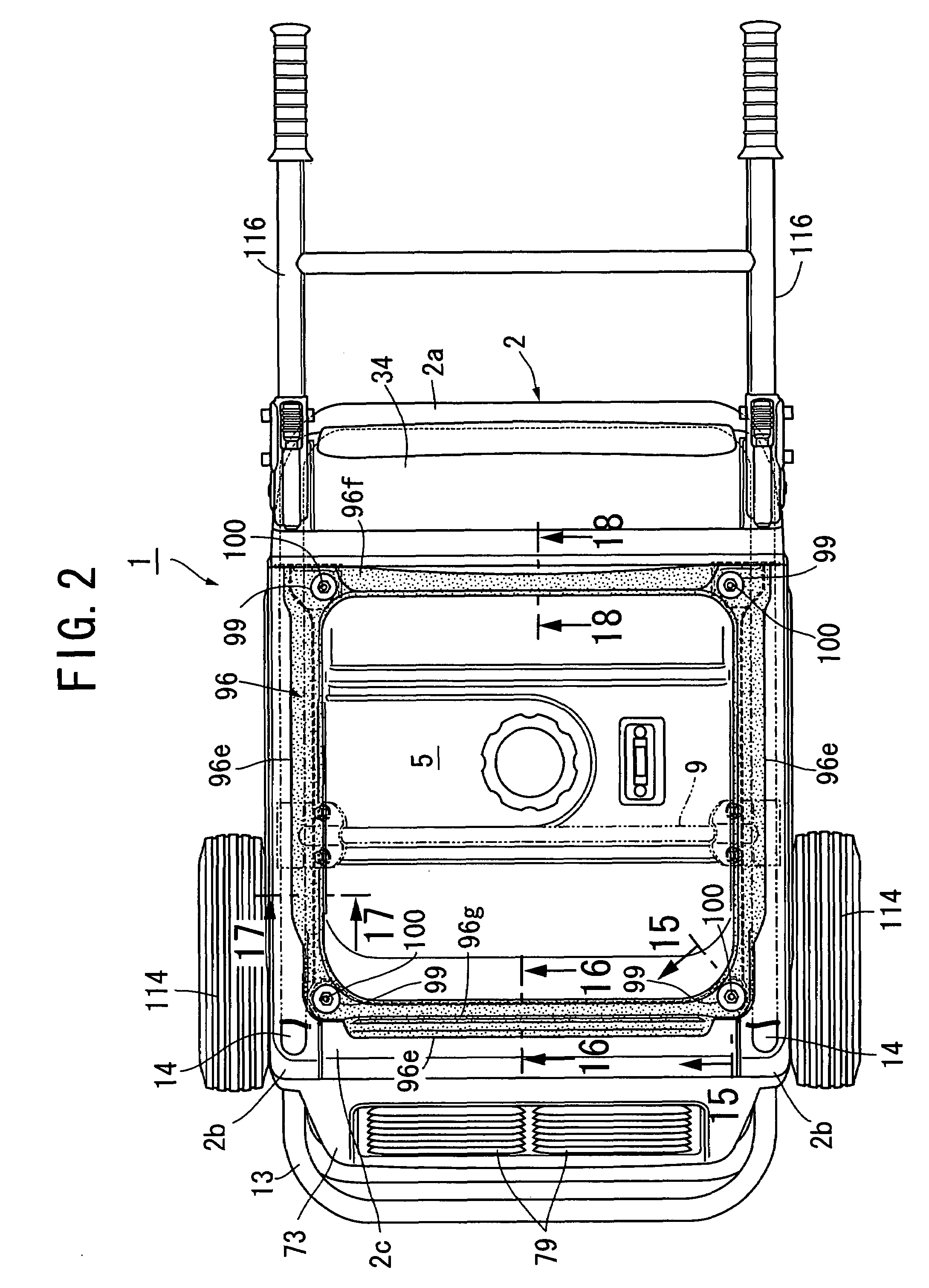
[0040]Referring to FIGS. 1 to 5 and 7, an engine-driven generator system 1 according to the present invention includes a frame 2, an engine 3 and a generator 4 (see FIG. 7). The engine 3 and the generator 4 are resiliently supported on a lower portion of the frame 2. A fuel tank 5 is mounted on an upper portion of the frame 2, along with a control unit 53 for the engine 3.

[0041]As shown in FIGS. 1, 2 and 6, the frame 2 includes a frame bottom portion 2a formed by bending a steel pipe into a rectangular parallelepiped shape, left and right sidewall plates 2b, 2b welded to the left and right longer sides of the frame bottom portion 2a, respectively, so as to extend upward therefrom, and an upper cross member 2c which connects rear upper ends of the sidewall plates 2b, 2b. Each of the sidewall plates 2b, 2b is made of steel.

[0042]A bumper 13 is secured to rear intermediate portions of the left and right sidewall plates 2b, 2b, thereby connecting the rear intermediate portions to each o...


PUM


Abstract

A duct member is disposed around outer peripheries of an engine and an engine-driven generator to define a continuous cooling-air passage between the duct member and the outer peripheries. A cooling fan is disposed in the cooling-air passage to generate a flow of cool air from one end of the cooling-air passage to the other end during operation of the engine. An exhaust muffler of the engine is disposed in the vicinity of the other end of the cooling-air passage. An air guide plate is connected to the duct member and is suspended from an upper portion of the duct member to cover an upper portion of one side face of the exhaust muffler which is opposite the cooling-air passage so that the air guide plate guides the cooling air flowing out of the cooling-air passage downward along the one side face of the exhaust muffler.

Description

RELATED APPLICATION DATA[0001]The present invention is based upon Japanese priority application No. 2006-228911, which is hereby incorporated in its entirety herein by reference.BACKGROUND OF THE INVENTION[0002]1. Field of the Invention[0003]The present invention relates to an engine-driven work machine connected to and driven by an engine. The work machine includes a duct member disposed around outer peripheries of the engine and the work machine to define a continuous cooling-air passage between the duct member and the outer peripheries. A cooling fan is disposed in the cooling-air passage to generate cooling air flowing from one end of the cooling-air passage to the other end during operation of the engine. An exhaust muffler of the engine is disposed in the vicinity of the other end of the cooling-air passage, wherein the exhaust muffler is cooled by the cooling air flowing out of the cooling-air passage. The work machine driven by the engine encompasses a generator, an air comp...

Claims


Application Information

Patent Timeline
Patent Type & Authority Patents(United States)
IPC IPC(8): F01P1/06
CPCF01P5/06F01P2001/005
Inventor ONODERA, TAIYOOKABE, KAKU
Owner HONDA MOTOR CO LTD
Why Eureka
Try Eureka