Printing control device, printing control system, and printing control method

a printing control and control device technology, applied in the direction of digital output to print units, instruments, digitally marking record carriers, etc., can solve the problems of not being able to achieve the output of printing operations as desired by users, taking time to obtain monochrome prints, and printing operations that cannot be performed with the conditions desired by users

Active Publication Date: 2008-07-15
PATOIS TELECOM LIMITED LIABILITY
View PDF7 Cites 31 Cited by
  • Summary
  • Abstract
  • Description
  • Claims
  • Application Information

AI Technical Summary

Benefits of technology

[0013]The present invention is achieved in finding a way to solve the foregoing problems, and it is therefore an object of the present invention to provide a printing control device, a printing control system and a printing control method, that permit the setting of print controlling conditions to be set in the printing device to be defined for each user. It is another object of the present invention to provide a printing control device, a printing control system and a printing control method wherein when a need arises to change a printing condition in a requested printing process for a restriction on a print processing function in the printing process as defined for each user, the user can select a print processing function as desired from print processing functions that are not restricted, without automatically changing to the printing condition set beforehand.
[0022]The foregoing structure wherein the detecting section detects the information on the restricted function as stored in the printing control device offers the effect of defining a printing control condition with a predetermined restricted print processing function for each printing control device. As a result, it is possible to restrict a printing process to be executed in the printing device for each printing control device.
[0023]Furthermore, the user of the printing control device can recognize the print processing conditions available in the printing process without restriction and restricted print processing conditions. It is therefore possible for the printing control device to control the printing process at the printing device so as to execute a printing process as desired by the user based on the option selected by the user among the available printing conditions.
[0028]The foregoing structure of the present invention offers the effect of restricting a printing process to be executed by the printing device for each information processing device by the printer driver. Then, by selecting at least one print processing function from the printing control conditions, it is possible to control a printing process in the printing device so as to execute the printing process as user desires.
[0032]According to the foregoing structure, the printer driver module is installed for each information processing device based on the information on restricted function. Therefore, the printing process to be executed at the printing device in response to the request from the information processing device is performed with the print processing function corresponding to the printer driver module. Namely, by installing a specific printer driver module from the server in the information processing device, it is possible to restrict the printing process to be executed at the printing device according to the printer driver module.

Problems solved by technology

However, as described in the foregoing printers, the printing conditions as requested by the user are changed automatically, and therefore, the printing operation may not be performed with the conditions desired by the user.
Generally, the amount of data for color print is larger than the amount of data for monochrome printing, and therefore, it takes time to obtain a monochrome print.
Besides, in the case where the printing conditions are changed automatically from the color printing to the monochrome printing, a file for monochrome printed sheets is prepared, and the printing conditions are set by the printer driver automatically, thereby presenting the problem that printed outputs as desired by the user may not be obtained.
Furthermore, in the case where the feed tray is changed automatically with the restriction on the print processing function, the feed tray as set automatically may not be the one the user desires.
As described, according to the foregoing structure wherein the printing conditions are changed automatically, an unnecessary longer time is required for the printing operation, or the printing operation may not be performed with the printing condition as user desires.
Incidentally, the patent document 1 discloses the structure wherein the printer driver is installed automatically in the host computer; however, it fails to disclose the structure wherein a restriction on a print processing function is set for each host computer (user), or the structure wherein the print processing function is restricted on the printer driver.

Method used


Image

  • Printing control device, printing control system, and printing control method
  • Printing control device, printing control system, and printing control method
  • Printing control device, printing control system, and printing control method

Examples


first embodiment

[0047]The following descriptions will explain one embodiment of the present invention in reference to FIG. 1 to FIG. 6.

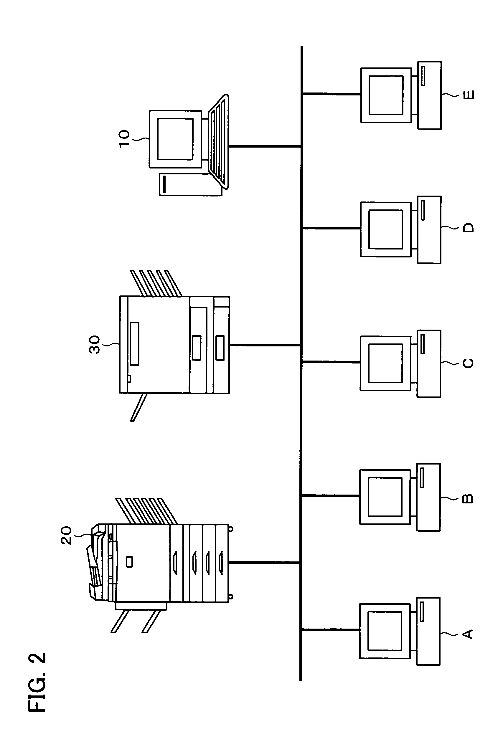
[0048]As illustrated in FIG. 2, a printer network system (printing control system) in accordance with the present embodiment includes a server 10, printers 20 and 30 (printing device) and host computers (hereinafter referred to as hosts) A to E (printing control device) that are mutually connected via a local area network (LAN) 40 (network).

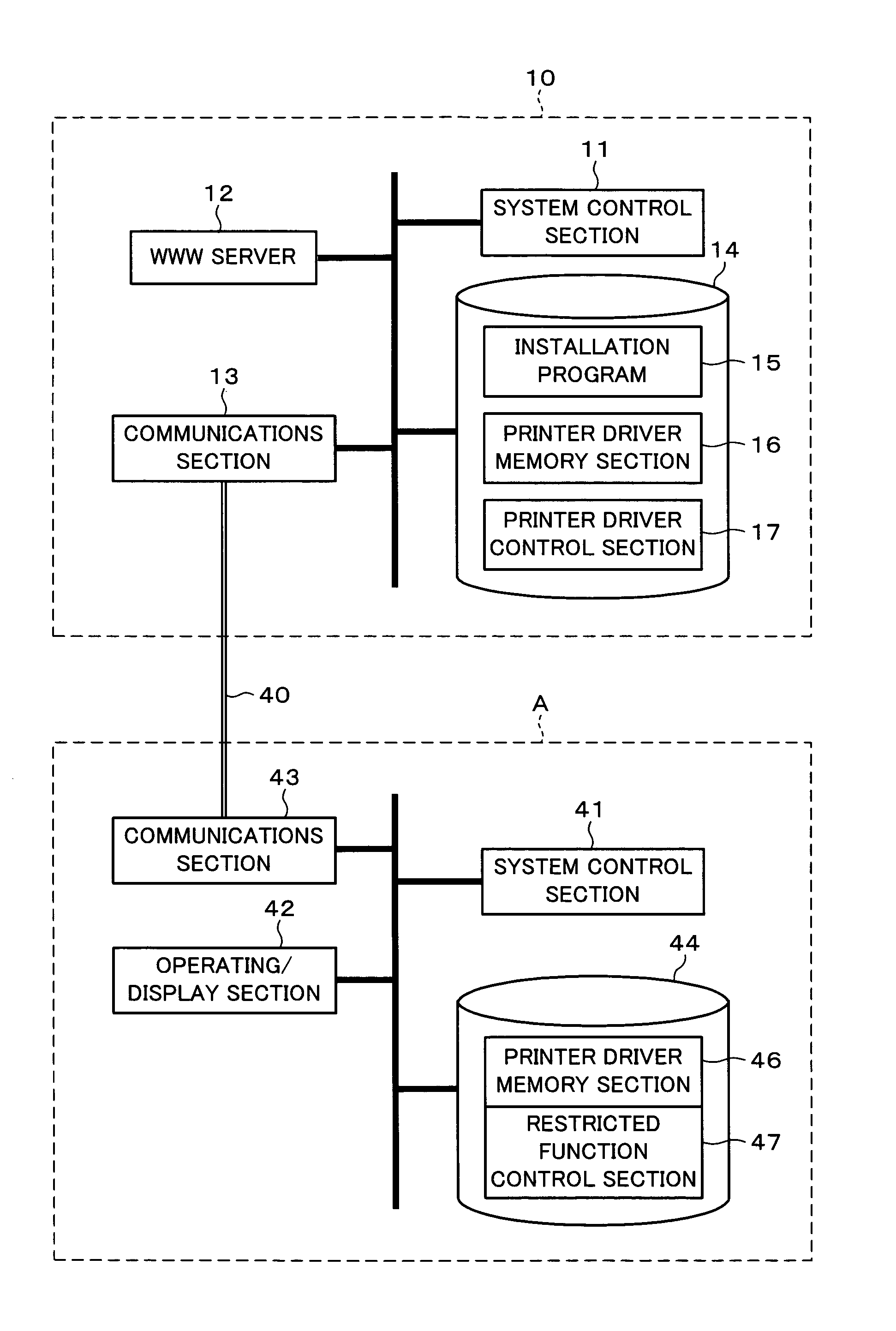
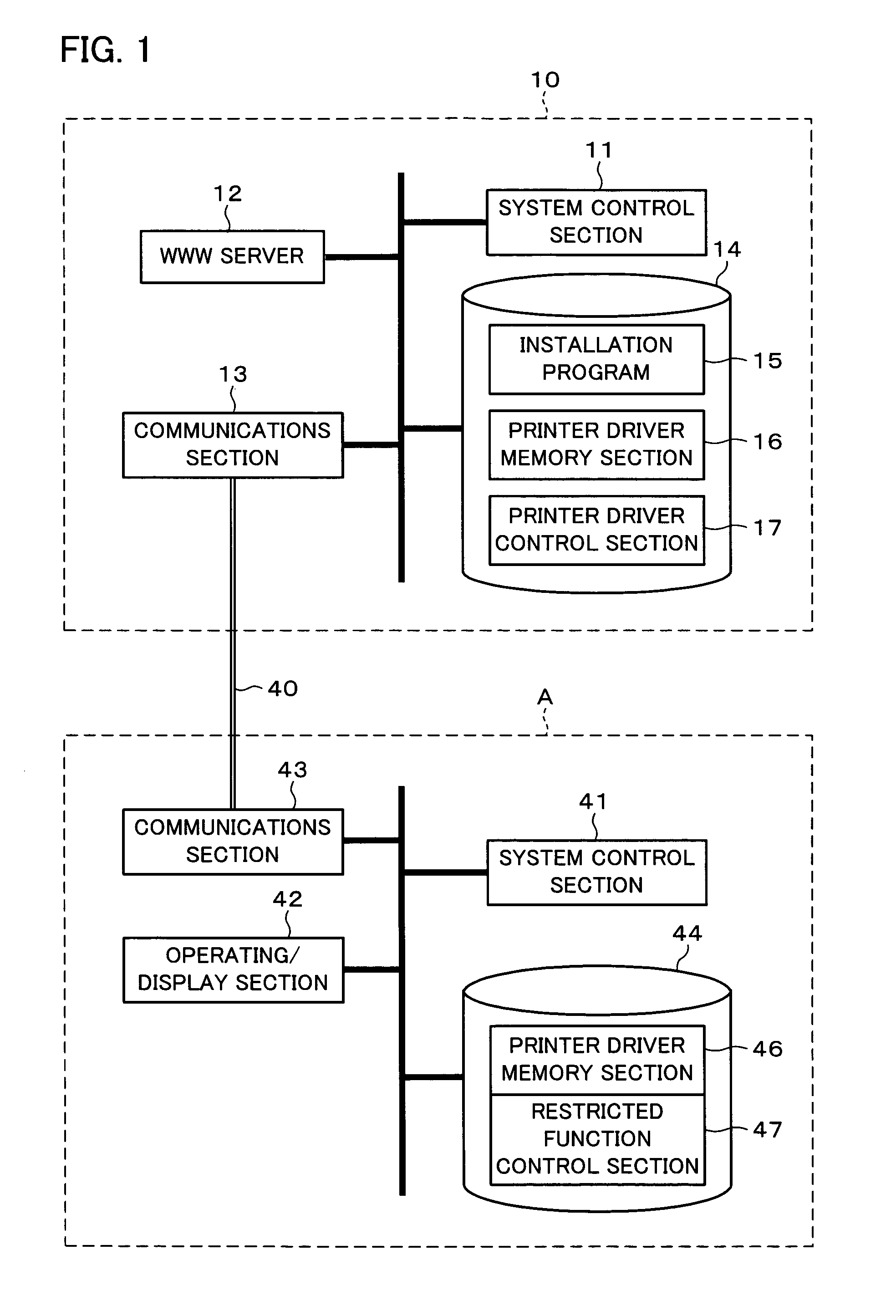
[0049]As illustrated in FIG. 1, the server 10 includes a system control section 11, a WWW (World Wide Web) server 12, a communications section 13 and a hard disk (hereinafter referred to as HD) 14.

[0050]The system control section 11 controls the server 10 on the whole, and controls operations of the WWW server 12, the control section 13 and the HD 14. The WWW server 12 controls the Web information to be provided via the network. The communications section 13 connect the server 10 and hosts A to E or the printers 20 and 30 (FIG. 2...

second embodiment

[0088]The following descriptions will explain another embodiment of the present invention in reference to FIG. 7 to FIG. 11. For ease of explanation, members (structures) having the same functions as those shown in the drawings pertaining to the first embodiment above will be given the same reference symbols, and explanation thereof will be omitted here.

[0089]As illustrated in FIG. 7, the printer network in accordance with the present embodiment is provided with a host X in replace of the host A adopted in the first embodiment. The host X includes a real time clock (hereinafter referred to as RTC) 45 in addition to the structure of the host A shown in FIG. 1. This RTC 45 controls a calendar (time, date, week, month, etc.). Each of the hosts B′ to E′ having the foregoing embodiments includes the RTC 45 in addition to the structure of the host B to E adopted in the first embodiment respectively. In the following, explanations will be given through an example of the host X; however, th...

third embodiment

[0108]The following descriptions will explain still another embodiment of the present invention in reference to FIG. 12. For ease of explanation, members (structures) having the same functions as those shown in the drawings pertaining to the first and second embodiments above will be given the same reference symbols, and explanation thereof will be omitted here.

[0109]In the foregoing first and second embodiments, explanations have been given through the case of installing the printer driver having all the functions from the server 10 the host A or X. In the present embodiment, explanations will be given through the case of installing a function module having a specific print processing function in replace of the printer driver having all the print processing functions.

[0110]Specifically, as illustrated in FIG. 12, the printer network system of the present embodiment is provided with a host Y in replace of the host A adopted in the first embodiment. The host Y basically has the same ...


PUM


Abstract

A printing control system of the present invention is arranged so as to control a printing process to be executed by a printer by a printer driver installed in a host computer. The host computer stores information on restricted function in HD for controlling the printing process to be executed by a computer. The printer driver includes a detecting section for detecting the information on the restricted function, and a defining section for defining as print controlling conditions, the print processing function available in the print processing based on the information on restricted function as defected by said detecting section. With this structure, it is possible to define the setting of the print controlling conditions in the printing device for each user.

Description

[0001]This Non-provisional application claims priority under 35 U.S.C. § 119(a) on Patent Application No. 2003 / 010260 filed in Japan on Jan. 17, 2003, the entire contents of which are hereby incorporated by reference.FIELD OF THE INVENTION[0002]The present invention relates to a printing control device connected to a printing device via a network, that makes the printing device execute a printing process, a printing control system that permits a printing control condition to be set in the printing device for each user, for example, by a printer driver, and also relates to a printing control method.BACKGROUND OF THE INVENTION[0003]In recent years, network connectable printers that can accept print jobs from a plurality of host computers linked in a LAN (Local Area Network) or other network have become prevalent, for example, in offices. In the case of adopting the foregoing network connectable printer, a host computer installs a printer driver for the control of the printing process ...

Claims


Application Information

Patent Timeline
Patent Type & Authority Patents(United States)
IPC IPC(8): G06K15/00B41J29/38G06F3/12
CPCG06F3/1205G06F3/1288G06F3/1253G06F3/1239G06F3/1208G06F3/1286
Inventor HONMA, TOMOYUKI
Owner PATOIS TELECOM LIMITED LIABILITY
Why Eureka
Try Eureka