Method of controlling access to control registers of a microprocessor

Inactive Publication Date: 2008-07-15
ADVANCED SILICON TECH
View PDF9 Cites 107 Cited by
  • Summary
  • Abstract
  • Description
  • Claims
  • Application Information

AI Technical Summary

Benefits of technology

[0016]In another embodiment, a processor having a normal execution mode and a secure execution mode may include execution logic, a control register and protection logic coupled to the control register. The control register may be configured to store state and mode information. The protection logic

Problems solved by technology

Further, the protection logic may include security logic which may selectivel

Method used


Image

  • Method of controlling access to control registers of a microprocessor
  • Method of controlling access to control registers of a microprocessor
  • Method of controlling access to control registers of a microprocessor

Examples


Embodiment Construction

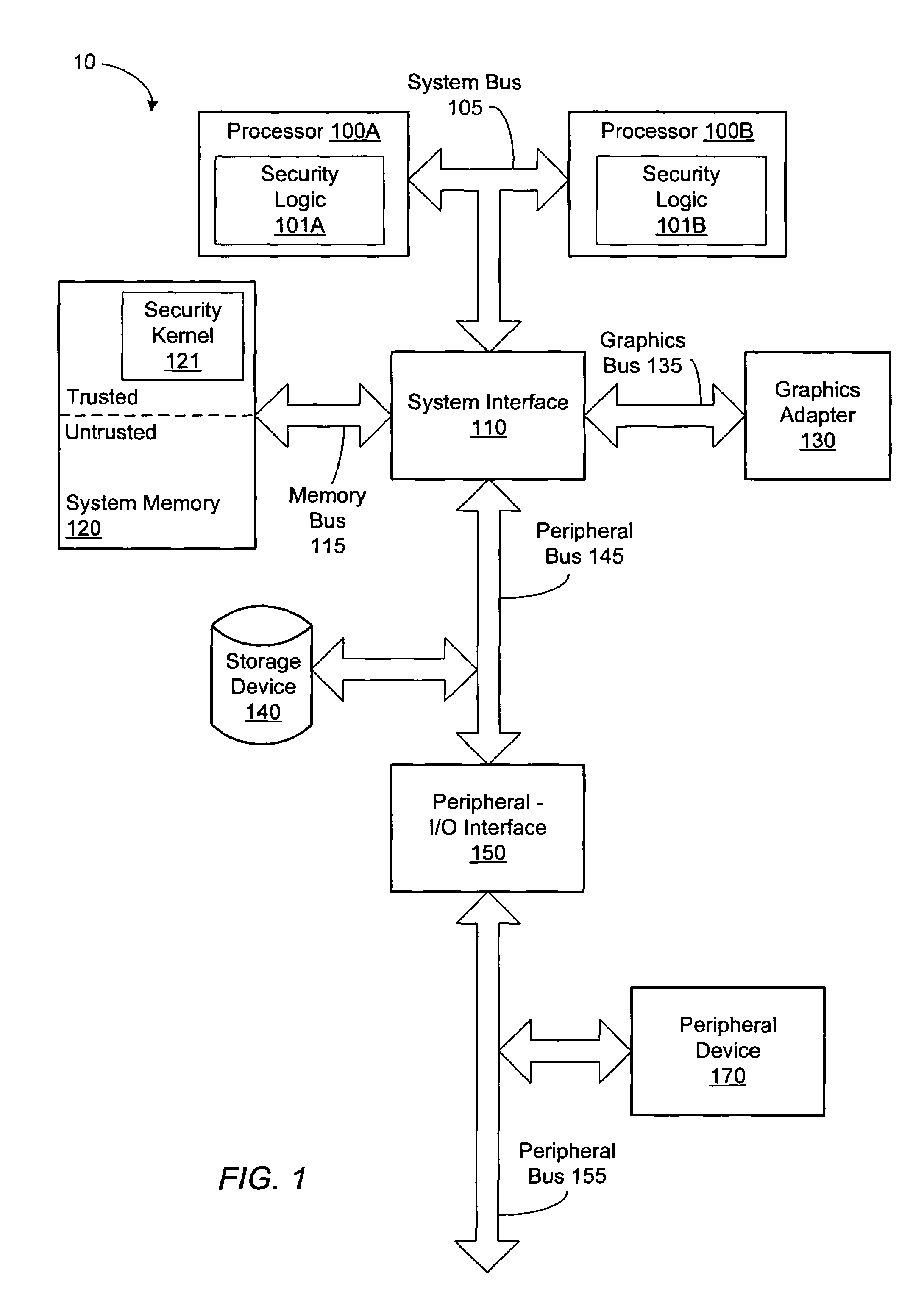
[0028]Turning now to FIG. 1, a block diagram of one embodiment of a computer system 10 is shown. Computer system 10 includes a microprocessor 100A and a microprocessor 1001B each coupled to a system interface 110 via a system bus 105. Microprocessor 100A and 100B include a security logic 101A and 101B, respectively. System interface 110 is coupled to a graphics adapter 130 via a graphics bus 135, a system memory 120 via a memory bus 115, to a peripheral interface 150 and to a storage device 140 via a peripheral bus 145. Peripheral interface 150 is coupled to a peripheral device 170 via a peripheral bus 155. It is noted that although two processors 100A and 100B are shown coupled to system interface 105, it is contemplated that other embodiments may include other numbers of processors. It is further noted that components having the same reference number may be referred to using only the reference number. It is also noted that microprocessors are commonly referred to as processors. Fo...


PUM


Abstract

A method of controlling access to a control register of a microprocessor. The method of controlling access to a control register of a processor having a normal execution mode and a secure execution mode may include storing state and mode information in the control register, allowing a software invoked write access to modify the state and mode information within the control register during the normal execution mode and selectively inhibiting the software invoked write access during the secure execution mode.

Description

[0001]This application claims the benefit of U.S. Provisional Application No. 60 / 373,571 filed Apr. 18, 2002.BACKGROUND OF THE INVENTION[0002]1. Field of the Invention[0003]This invention relates to computer systems and, more particularly, to protecting data stored within the computer system memory from unauthorized access.[0004]2. Description of the Related Art[0005]Modern computer systems are revolutionizing the way people live. This is particularly true for system platforms including microprocessors employing the x86 system architecture. The openness of the x86 architecture to a myriad of owner-installable third-party peripheral devices and applications has enabled a broad marketplace of hardware and software vendors that has fostered competition, innovation, and evolution. An example of such evolution is the now widespread use of the platform as a digital communication and media system of ever-increasing quality and capability. In concert with the Internet, these system platform...

Claims


Application Information

Patent Timeline
IPC IPC(8): G06F7/04G06F12/00H04L9/32G06F13/00H04L9/00G06F9/445G06F21/60G06F21/12
CPCG06F9/4403G06F21/74G06F21/10G06F1/00G06F9/00
Inventor CHRISTIE, DAVID S.MCGRATH, KEVIN J.
Owner ADVANCED SILICON TECH
Why Eureka
Try Eureka