

Volume-filling mechanical assemblies and methods of operating the same
a technology of mechanical assemblies and mechanical components, applied in the direction of roofs, bumpers, pedestrian/occupant safety arrangements, etc., to achieve the effect of expanding the volume filling structure, strengthening the vehicle member, and stiffening the expansion volume filling structur
- Summary
- Abstract
- Description
- Claims
- Application Information
AI Technical Summary
Benefits of technology
Problems solved by technology
Method used
Image

Examples
Embodiment Construction
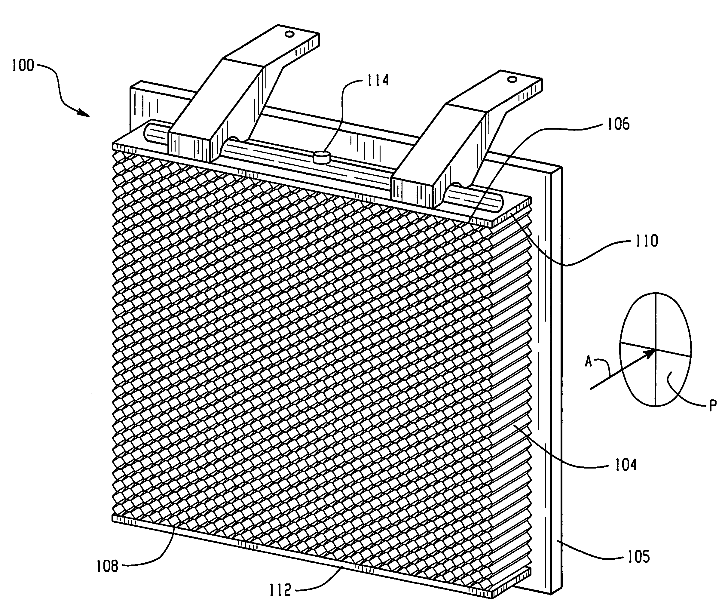
[0024]The present disclosure provides methods and apparatuses for activation of energy management structures. The energy management structures generally comprise an expandable volume-filling mechanical structure for both vehicle crash energy management and occupant / pedestrian protection applications. Advantageously, the expandable volume-filling mechanical structure, also referred to herein as the energy absorbing device, effectively absorbs the kinetic energy associated with an impact. As will be further described herein, suitable applications utilizing the energy absorbing device within or about a vehicle environment include, but are not intended to be limited to, crash energy dissipation, load path creation, modification of a vehicle deceleration pulse, local stiffening or reinforcement of the vehicle structure, stiffening or reinforcing closed section members subject to lateral loading, pedestrian impact protection, occupant protection, vehicle compatibility during impact events...
PUM
| Property | Measurement | Unit |
|---|---|---|
| temperature | aaaaa | aaaaa |
| temperature | aaaaa | aaaaa |
| temperature | aaaaa | aaaaa |
Abstract
Description
Claims
Application Information