
Honeycomb filter for exhaust gas decontamination

a technology of exhaust gas decontamination and honeycomb, which is applied in the direction of auxillary pretreatment, physical/chemical process catalysts, separation processes, etc., can solve the problems of affecting the permeability of gas discharged from internal exhaust, affecting the permeability of gas discharge, so as to achieve excellent strength and durability, and reduce thermal stress

Active Publication Date: 2007-12-18
IBIDEN CO LTD
View PDF58 Cites 91 Cited by
  • Summary
  • Abstract
  • Description
  • Claims
  • Application Information

AI Technical Summary

Benefits of technology

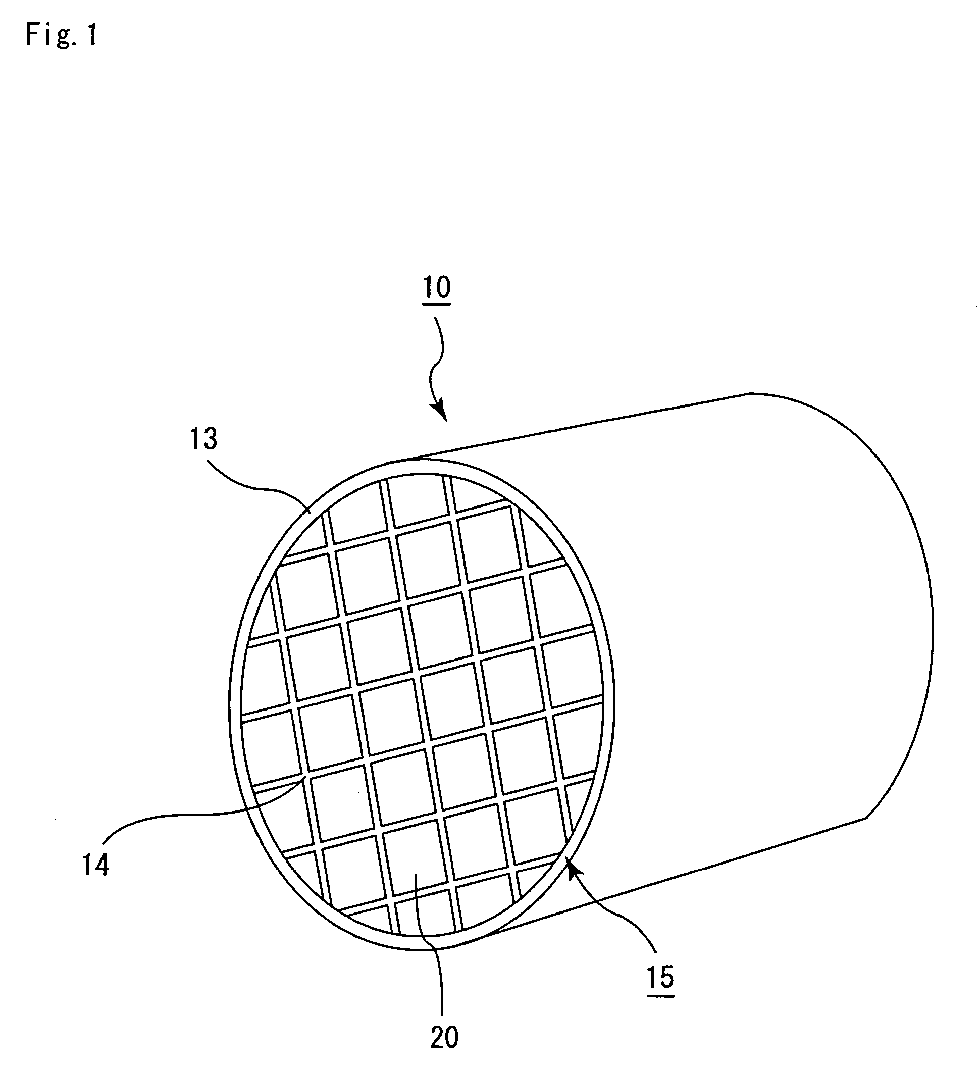
The present invention provides a honeycomb filter for purifying exhaust gases that can alleviate thermal stress, reduce the likelihood of cracks, and have excellent strength and durability. The honeycomb filter has a structure where multiple columnar porous ceramic members are combined with one another through an adhesive layer. The adhesive layer has a thermal expansion coefficient that matches that of the ceramic member, reducing the likelihood of cracks and other damage. The filter also has a small difference in thermal expansion between the adhesive layer and the ceramic member, which further improves its strength and durability.

Problems solved by technology

In recent years, particulates, contained in exhaust gases discharged from internal combustion engines of vehicles such as buses and trucks and construction machines, have raised serious problems since those particulates are harmful to the environment and the human body.
As such a purifying process for exhaust gases progresses, particulates are gradually accumulated on the partition wall that separates the through holes of the ceramic filter to cause clogging and the subsequent interruption in gas permeability.
In such a recycling process, however, it is difficult to evenly heat the ceramic filter, thus the heat is locally generated due to the burning of the particulates to cause a large thermal stress.
Moreover, even during normal operations, an uneven temperature distribution occurs inside the ceramic filter due to a thermal impact or the like derived from an abrupt temperature change in the exhaust gases, resulting in a thermal stress.
Consequently, in the case where the ceramic filter is constituted by a single ceramic member, cracks tend to be generated to cause a serious problem in collecting the particulates.
Moreover, in an attempt to produce a large-size ceramic filter, since firing shrinkage becomes greater upon firing, it becomes difficult to control the shape.
Therefore, when particulates are burned locally in the honeycomb filter, that is, when a local temperature change occurs therein, due to: uneven amounts of accumulated particulates; uneven amounts of catalyst in the case of allowing the honeycomb filter to support the catalyst; and unevenness of applied heat given by a heater, exhaust gases and the like, a great thermal stress is generated between the portion having this local temperature change and the other portions, with the result that cracks tend to be generated in the porous ceramic member and the adhesive layer.
However, in the case of the honeycomb filter in which Young's modulus of the adhesive layer is set to 20% or less of Young's modulus of the porous ceramic member and the honeycomb filter in which the material strength of the adhesive layer is made lower than the material strength of the porous ceramic member, the kinds of the materials of the adhesive layer and the porous ceramic member to be used are limited.
Moreover, even in the case of the above-mentioned honeycomb filters, when the coefficient of the thermal expansion of the porous ceramic member and the coefficient of the thermal expansion of the adhesive layer are equivalent to each other, in the case of occurrence of a local temperature change, it was not possible to sufficiently alleviate a great thermal stress, resulting in the problem of the generation of cracks in the porous ceramic member and the adhesive layer.

Method used


Image

  • Honeycomb filter for exhaust gas decontamination
  • Honeycomb filter for exhaust gas decontamination
  • Honeycomb filter for exhaust gas decontamination

Examples


example 1

[0113](1) Powder of α-type silicon carbide having an average particle size of 5 μm (60% by weight) and powder of β-type silicon carbide having an average particle size of 0.5 μm (40% by weight) were wet-mixed, and to 100 parts by weight of the resulting mixture were added and kneaded 5 parts by weight of an organic binder (methyl cellulose) and 10 parts by weight of water to obtain a kneaded matter. Next, after a slight amount of a plasticizer and a lubricant had been added to the kneaded matter and this had been further kneaded, the resulting kneaded matter was extrusion-molded, so that a raw formed product was manufactured.

[0114]Next, the above-mentioned raw formed product was dried by using a micro-wave drier, and predetermined through holes were then filled with a paste having the same composition as the raw formed product, and after this had been again dried by using a drier, this was degreased at 400° C., and sintered at 2200° C. in a normal-pressure argon atmosphere for 3 hou...

example 2

[0118](1) The same processes as (1) of Example 1 were carried out to obtain a porous ceramic member.

[0119](2) The same processes as Example 1 were carried out to manufacture a honeycomb filter except that, as a heat-resistant adhesive paste, the following paste was used: that is a paste prepared by adding 25 parts by weight of water to 100 parts by weight of a mixture composed of 15. 7% by weight of alumina fibers having a fiber length of 0.2 mm, 54.2% by weight of silicon carbide particles having an average particle size of 0.6 μm, 8.1% by weight of silica sol, 2.0% by weight of carboxy methyl cellulose and 20% by weight of ammonium hydrogen carbonate serving as a foaming agent, was used to manufacture a honeycomb filter.

example 3

[0120](1) The same processes as (1) of Example 1 were carried out to obtain a porous ceramic member.

[0121](2) The same processes as Example 1 were carried out to manufacture a honeycomb filter except that, as a heat-resistant adhesive paste, the following paste was used: that is, a paste prepared by adding 35 parts by weight of water to 100 parts by weight of a mixture composed of 13.7% by weight of alumina fibers having a fiber length of 0.2 mm, 47.4% by weight of silicon carbide particles having an average particle size of 0.6 μm, 7.1% by weight of silica sol, 1.8% by weight of carboxy methyl cellulose and 30% by weight of ammonium hydrogen carbonate serving as a foaming agent.


PUM

PropertyMeasurementUnit
temperatureaaaaaaaaaa
porosityaaaaaaaaaa
porosityaaaaaaaaaa

Abstract

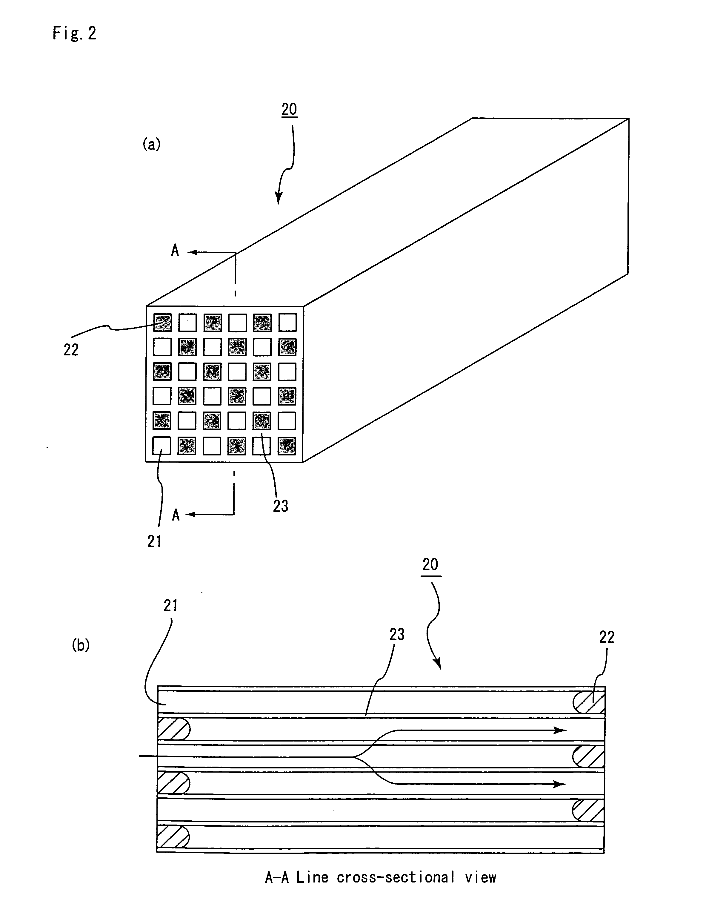
A honeycomb filter for purifying exhaust gases, which makes it possible to alleviate a thermal stress generated due to occurrence of a local temperature change, is less likely to generate cracks, and is excellent in strength and durability. The honeycomb filter has a structure in which a plurality of column-shaped porous ceramic members, each having a number of through holes that are placed side by side in the length direction with a partition wall interposed therebetween, are combined with one another through adhesive layers so that the partition wall that separates the through holes are allowed to function as a filter for collecting particulates. A thermal expansion coefficient αL of the adhesive layer and a thermal expansion coefficient αF of the porous ceramic member is as follows:0.01<|αL−αF| / αF<1.0.

Description

CROSS REFERENCE TO RELATED APPLICATION[0001]This application claims benefit of priority to Japanese Patent Application No. 2002-28644, filed on Feb. 5, 2002, the contents of which are incorporated by reference herein.TECHNICAL FIELD[0002]The present invention relates to a honeycomb filter for purifying exhaust gases, that is used as a filter for removing particulates and the like contained in exhaust gases discharged from an internal combustion engine such as a diesel engine.BACKGROUND ART[0003]In recent years, particulates, contained in exhaust gases discharged from internal combustion engines of vehicles such as buses and trucks and construction machines, have raised serious problems since those particulates are harmful to the environment and the human body.[0004]For this reason, there have been proposed various ceramics filters which allow exhaust gases to pass through porous ceramics to collect particulates in the exhaust gases, so that the exhaust gases can be purified.[0005]No...

Claims


Application Information

Patent Timeline
Patent Type & Authority Patents(United States)
IPC IPC(8): B01D46/00F01N3/022B01D46/24B01J35/04F01N3/035
CPCB01D46/2429B01D46/2448B01J35/04F01N3/0222Y10S55/10B01D46/2459B01D2046/2496F01N3/035F01N2260/10F01N2330/06F01N2330/30F01N2370/22Y02T10/20Y10S55/30B01D46/2444Y02T10/12B01D46/2498B01D46/24494B01D46/24493B01D46/2478B01J35/56
Inventor KUDO, ATSUSHIKUNIEDA, MASAFUMI
Owner IBIDEN CO LTD
Learn More