Wall mount with detachable support panel

a technology of support panel and wall mount, which is applied in the direction of fixed installation, lighting and heating apparatus, lighting support devices, etc., can solve the problems of unattractive or clashing mounting brackets, unwieldy size, shape and weight, etc., and achieve convenient access, safe and efficient securing, and facilitate electrical connection

Active Publication Date: 2008-07-22
IDEAL IND LIGHTING LLC
View PDF15 Cites 27 Cited by
  • Summary
  • Abstract
  • Description
  • Claims
  • Application Information

AI Technical Summary

Benefits of technology

[0006]Another object of the invention is to provide a novel apparatus for mounting a lighting fixture that allows the fixture to be mechanically secured to the apparatus in a convenient manner before having to perform any electrical connections to the fixture.
[0007]Another object of the invention is to provide an exceptional apparatus for mounting a lighting fixture having a support panel that permits the fixture to be maintained in an elevated position so as to facilitate making electrical connections during installation of the fixture as well as to provide convenient access to such connections afterwards.
[0008]Yet another object of the invention is to provide an excellent apparatus for mounting a lighting fixture having a support panel that is detachable from its mount housing to allow for safe and efficient securing of the fixture to the panel and to permit unobstructed access within the housing to the leads of the electrical conduit needed to power the fixture.
[0009]Still another object of the invention is to provide a desirable apparatus for mounting a lighting fixture that is simple and inexpensive to construct, highly reliable to use and pleasing in appearance.SUMMARY OF THE INVENTION

Problems solved by technology

Of particular concern, however, is that most lighting fixtures of this type are unwieldy in size, shape and weight, making them extremely difficult to handle when installed.
These fixtures also often use mounting brackets that are either unattractive or clash with the appearance of the lighting fixture or its surrounding building.
Both of these operations can be dangerous, however, when the installation is performed high above the ground from oftentimes only the top of a ladder.
Since either operation demands the use of two hands, the installer must find a way to support the fixture upon the ladder near him and yet leave unobstructed the needed workspace.
As a result, given the dimensions and weight of the lighting fixture, installation is usually accomplished in a manner contributing undue risk to the worker.

Method used


Image

  • Wall mount with detachable support panel
  • Wall mount with detachable support panel
  • Wall mount with detachable support panel

Examples


Embodiment Construction

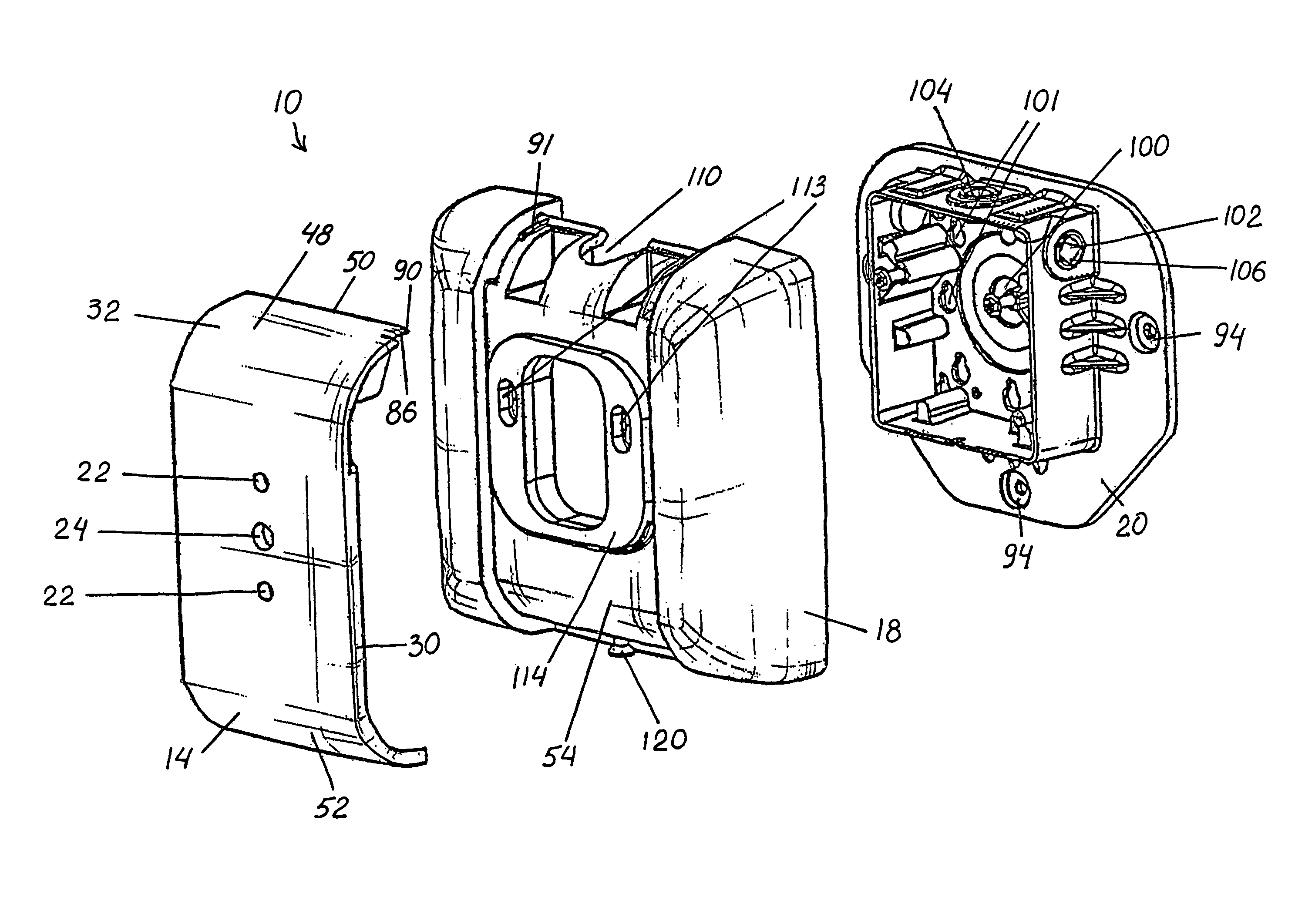
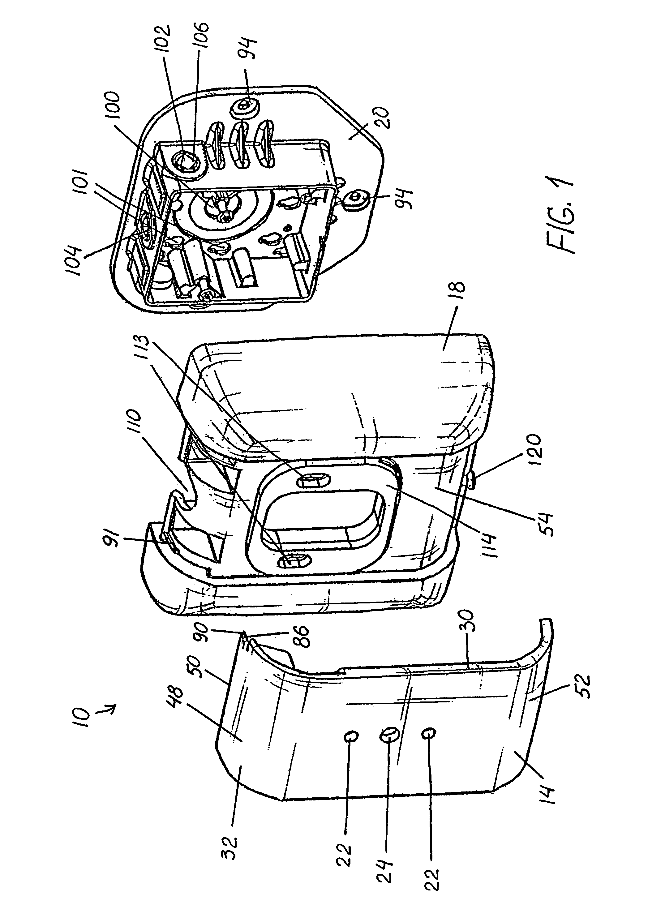
[0030]The drawings illustrate an improved apparatus 10 for mounting a lighting fixture 12 in accordance with this invention. Apparatus 10 includes support panel 14 and mount housing 16. As seen in the preferred embodiment shown in FIG. 1, mount housing 16 has housing cover 18 and wall bracket 20.

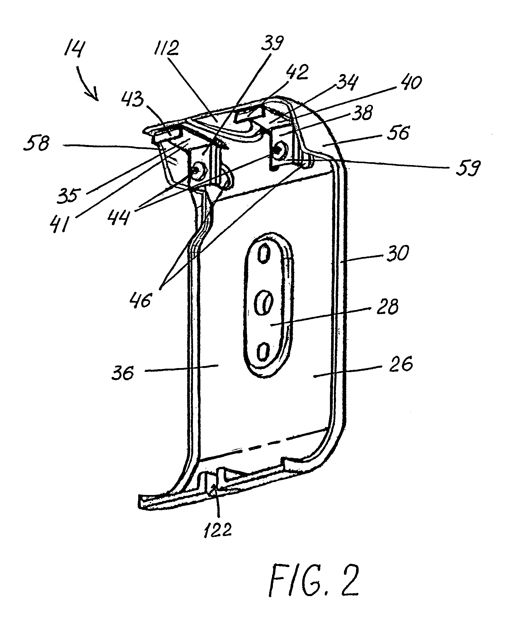
[0031]Support panel 14 is provided with two support apertures 22 and wiring aperture 24. When mounted, lighting fixture 12 is rigidly secured to support panel 14 by having two fasteners (not shown) received in each support aperture 22 from the rear wall of lighting fixture 12. The fasteners are preferably ⅝ inch bolts having a diameter appropriate for the size and weight of the fixture being mounted. As illustrated in FIG. 2, rear surface 26 of support panel 14 has reinforced portion 28 surrounding apertures 22, 24, adding depth to panel wall 30, to insure a firm engagement between fixture 12 and front surface 32 when securing the bolts in place with corresponding nuts (not shown).

[0032]As s...


PUM


Abstract

An apparatus for mounting a lighting fixture is provided having a mount housing with at least one pivot portion and a support panel with at least one hook portion, the support panel being attached to the mount housing in a manner where the hook portion can slide and pivot with respect to the pivot portion. The pivot portion includes a rail, a tab-slot and a tab-rest, the tab-slot and tab-rest being adjacent to the rail and the hook portion has a hook member and a tab-stand adjacent to the hook member. The support panel is free to move between an open and a closed position and, preferably, detachable from the mount housing. A method for mounting a lighting fixture is also disclosed.

Description

FIELD OF THE INVENTION[0001]This invention is related generally to apparatus for mounting lighting fixtures and, more particularly, to apparatus for mounting lighting fixtures having a slidable and pivotable support panel.BACKGROUND OF THE INVENTION[0002]A wide variety of flood and area lighting fixtures exist to provide illumination of buildings, parking lots, walkways and the like. Such fixtures are frequently mounted high in the air on the walls of buildings where they can only be installed with the assistance of a ladder or aerial lift. Of particular concern, however, is that most lighting fixtures of this type are unwieldy in size, shape and weight, making them extremely difficult to handle when installed. These fixtures also often use mounting brackets that are either unattractive or clash with the appearance of the lighting fixture or its surrounding building.[0003]Installation of a flood or area lighting fixture requires that it first be properly connected electrically to th...

Claims


Application Information

Patent Timeline
Patent Type & Authority Patents(United States)
IPC IPC(8): F21S8/00F21S13/02
CPCF21V21/02F21S8/033
Inventor HAUGAARD, ERIC J.WILCOX, KURT S.
Owner IDEAL IND LIGHTING LLC
Why Eureka
Try Eureka