Fusible conductive ink for use in manufacturing microfluidic analytical systems

a microfluidic and analytical system technology, applied in the field of analytical devices, can solve the problems of microchannels and surrounding structures, (s) and electrodes) can suffer from a lack of unified structural integrity, and control is problemati

Active Publication Date: 2008-07-22
LIFESCAN IP HLDG LLC
View PDF40 Cites 103 Cited by
  • Summary
  • Abstract
  • Description
  • Claims
  • Application Information

AI Technical Summary

Benefits of technology

[0011]Fusible conductive inks according to the present invention can be employed in the manufacturing of microfluidic systems to form electrodes, electrically conductive traces and / or electrically conductive contact pads. In addition, since the fusible conductive inks are fusible, electrodes and electrically conductive traces formed from the inks can be fused with insulating substrates and laminate layers to aid in the formation of liquid and / or air tight microchannels. Furthermore, electrically conductive traces formed from the inks can be fused with electrically conductive contact pads to provide a secure and robust electrical connection between the electrically conductive contact pads and an electrode via the electrically conductive trace.

Problems solved by technology

The relatively small size of the fluid samples and microchannels in microfluidic analytical devices can, however, render such control problematic.
For example, microchannels and surrounding structures (e.g., substrate(s) and electrode(s)) can suffer from a lack of unified structural integrity such that the microchannels are not adequately liquid and / or air tight.
However, the electrodes employed in microfluidic analytical devices are relatively small and can be fragile in nature.
As a consequence, the electrodes are susceptible to incomplete or weak electrical contact resulting in the creation of spurious and / or deleterious signals during operation.

Method used


Image

  • Fusible conductive ink for use in manufacturing microfluidic analytical systems
  • Fusible conductive ink for use in manufacturing microfluidic analytical systems
  • Fusible conductive ink for use in manufacturing microfluidic analytical systems

Examples


example

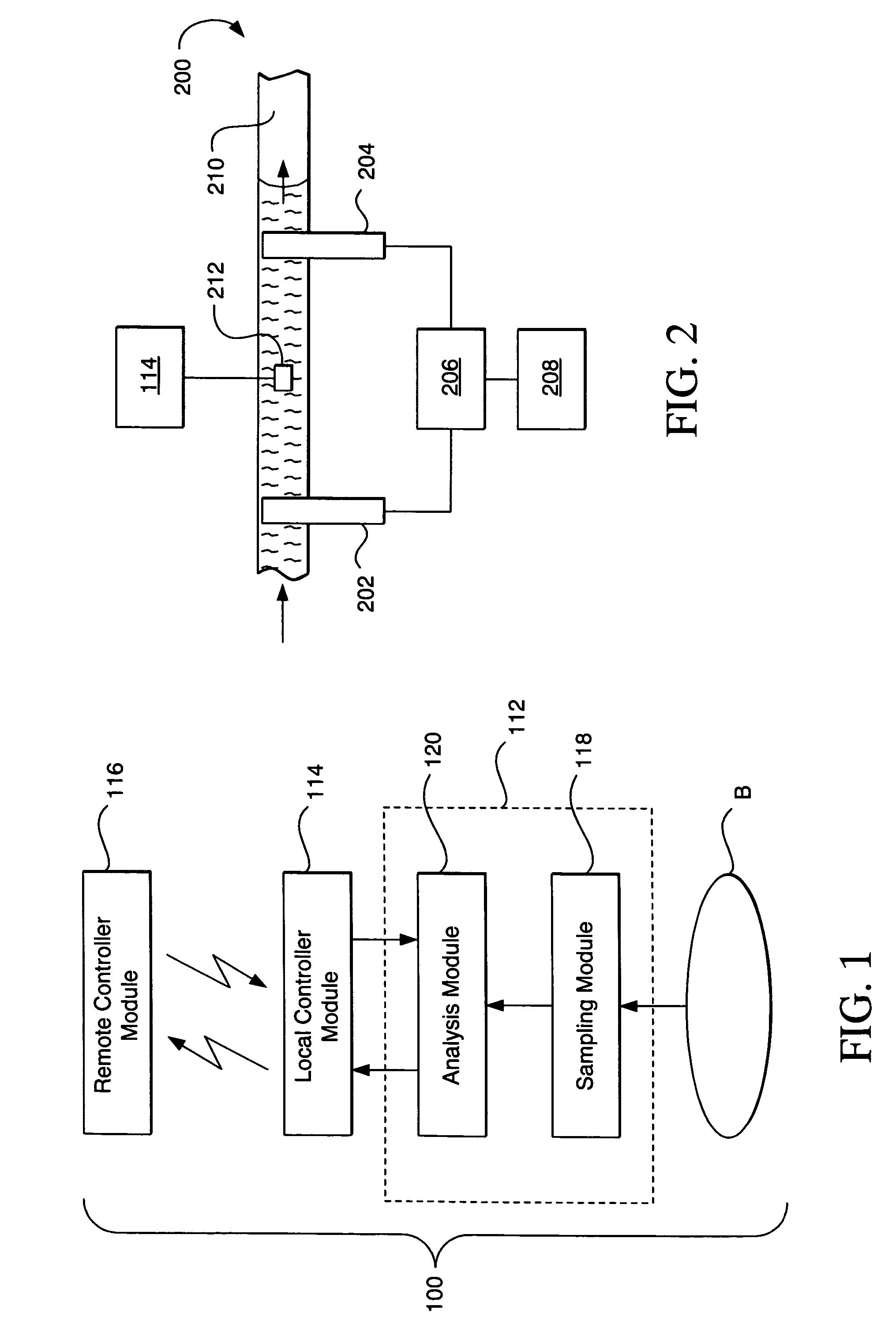
Manufacturing of an Analysis Module

[0058]An embodiment of a microfluidic analytical device according to the present invention was manufactured using an insulating substrate formed from a polystyrene material (i.e., Polystyrol 144C, commercially available from BASF, Aktiengesellschaft, Business Unit Polystyrene, D-67056 Ludwigshafen, Germany) and a laminate layer formed from another polystyrene material (i.e., Norflex® Film, commercially available from NSW Kunststofftechnik, Norddeutsche Seekabelwerke AG, 26954 Nordenham, Germany).

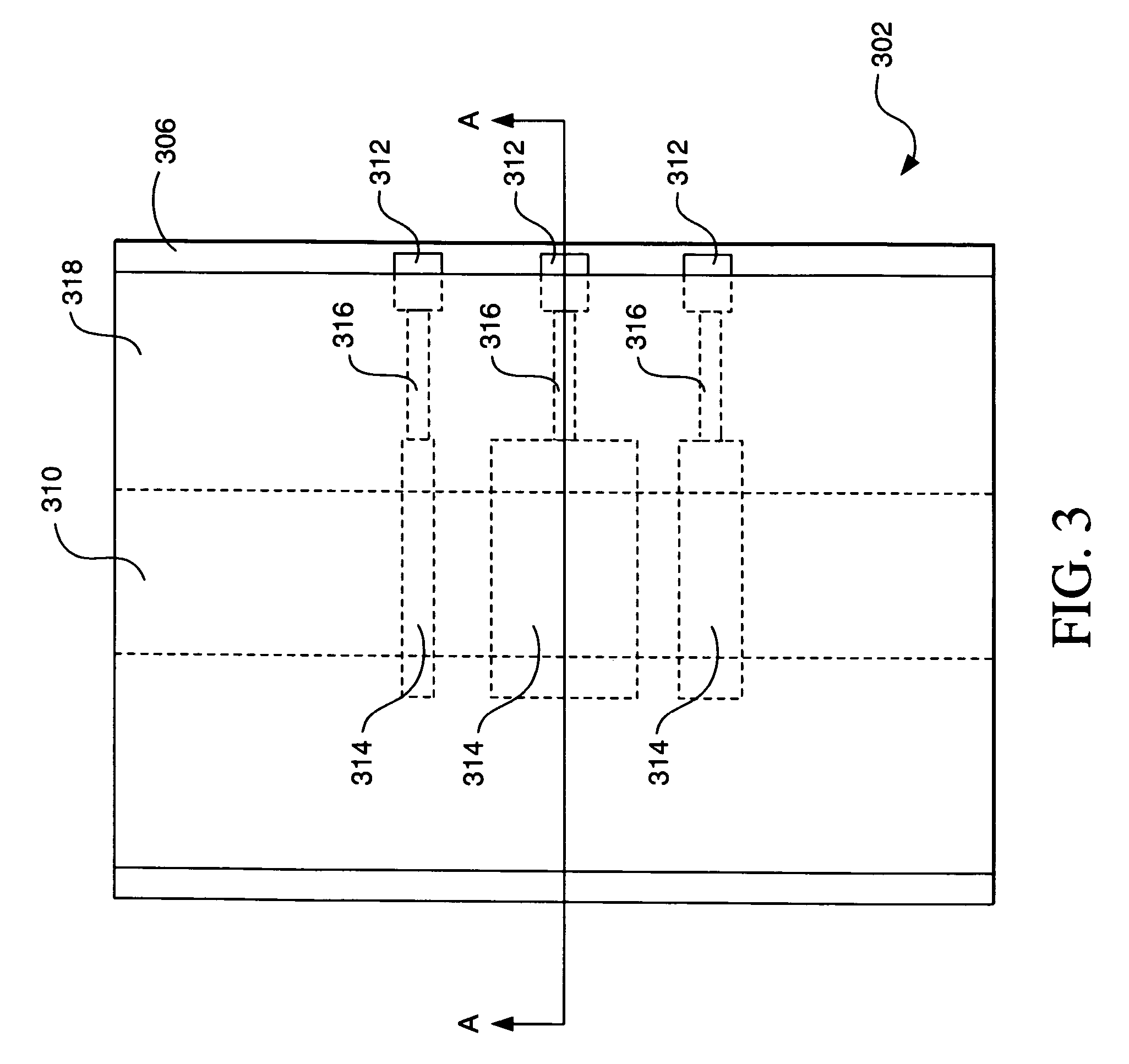
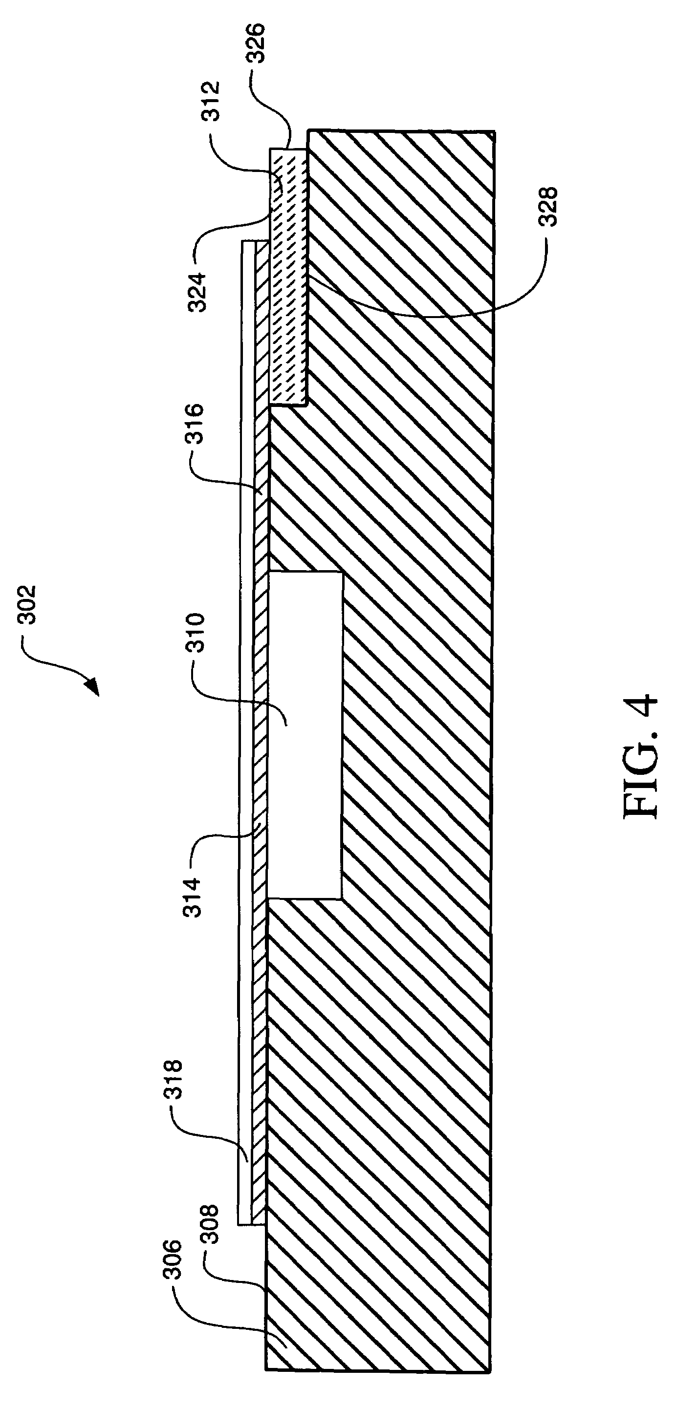
[0059]Electrodes and electrically conductive traces were printed on the laminate layer using a conductive ink. In addition, electrically conductive contact pads were printed on the insulating substrate using the same conductive ink. The conductive ink used to print the electrically conductive traces, electrically conductive contact pads and electrodes had the following mass percent composition:[0060]18.5% micronised powder containing platinum and carbon in ...


PUM

PropertyMeasurementUnit
volumeaaaaaaaaaa
thicknessaaaaaaaaaa
thicknessaaaaaaaaaa

Abstract

A fusible conductive ink for use in manufacturing microfluidic analytical systems includes micronised powder containing platinum and carbon, poly(bisphenol A-co-epichlorohydrin)-glycidyl end capped polymer, and a solvent. In addition, the ratio of micronised powder to poly(bisphenol A-co-epichlorohydrin)-glycidyl end capped polymer is in the range of 3:1 to 1:3. The fusible conductive inks can be employed in the manufacturing of microfluidic systems to form electrodes, electrically conductive traces and / or electrically conductive contact pads.

Description

BACKGROUND OF THE INVENTION[0001]1. Field of the Invention[0002]The present invention relates, in general, to analytical devices and, in particular, to materials for use in manufacturing microfluidic analytical systems.[0003]2. Description of the Related Art[0004]In analytical devices based on fluid samples (i.e., fluidic analytical devices), the requisite fluid samples should be controlled with a high degree of accuracy and precision in order to obtain reliable analytical results. Such control is especially warranted with respect to “microfluidic” analytical devices that employ fluid samples of small volume, for example, 10 nanoliters to 10 microliters. In such microfluidic analytical devices, the fluid samples are typically contained and transported in microchannels with dimensions on the order of, for example, 10 micrometers to 500 micrometers.[0005]The control (e.g., transportation, position detection, flow rate determination and / or volume determination) of small volume fluid sa...

Claims


Application Information

Patent Timeline
Patent Type & Authority Patents(United States)
IPC IPC(8): C09D11/00C09D11/10
CPCC09D11/102C09D11/52H01B1/22G01N27/02G01N37/00
Inventor RODGERS, JAMES IAINMACLENNAN, MARGARETMOFFAT, JAMESMCNEILAGE, ALAN
Owner LIFESCAN IP HLDG LLC
Why Eureka
Try Eureka