Corrosion-Resistant Downhole Transmission System

a transmission system and downhole technology, applied in the direction of borehole/well accessories, coupling device connections, survey, etc., can solve the problems of corrosive nature of downhole drilling environment, gradual disintegration and deterioration of steel and other metals that make up the drill string, and achieve the effect of reducing corrosion

Inactive Publication Date: 2005-07-14
INTELLISERV
View PDF63 Cites 129 Cited by
  • Summary
  • Abstract
  • Description
  • Claims
  • Application Information

AI Technical Summary

Benefits of technology

[0009] The present invention has been developed to provide apparatus and methods for reducing corrosion in downhole transmission systems that overcome many or all of the above-discussed problems.
[0012] In certain embodiments, the annular housing may be characterized as having a first contact and the annular recess may be characterized as having a second contact in contact with the first contact. Because the annular housing may move with respect to the annular recess, the first contact may be adapted to slide or move with respect to the second contact. In selected embodiments, a lubricant may be deposited on the contact surfaces to reduce wear therebetween.
[0013] In certain embodiments, the diameter of the annular housing may be slightly smaller than the diameter of the annular recess. When the annular housing is installed into the annular recess, this slight size difference may create enough force to keep the contact surfaces pressed together. The slight size difference may also be sufficient to create a bias (ie., a spring-like force) between the annular housing and the annular recess that urges the annular housing out of the annular recess. In certain embodiments, corresponding shoulders may be formed on the annular housing and in the annular recess to keep the annular housing retained within the recess.
[0016] In another embodiment, an apparatus in accordance with the invention may include a downhole tool having a first end, a second end, and an annular recess formed in at least one of the first end and the second end. An annular transmission element is installed in the annular recess. The annular transmission element includes an electrically-conductive annular housing which resides in and electrically contacts the annular recess. A coating is attached to the annular housing, the annular recess, or both, and is adapted to increase their resistance to corrosion while maintaining electrical conductivity between the two.

Problems solved by technology

However, due to the complexity, expense, and unreliability of such systems, many attempts to create such a system have failed to achieve significant commercial acceptance.
One obstacle to implementing a “downhole transmission system” is the corrosive nature of a downhole drilling environment.
As a result, steel and other metals that make up the drill string are gradually disintegrated and deteriorated by the corrosive downhole environment.
Formation fluids, drilling mud, stress corrosion, and erosion from cuttings may all contribute to drill string corrosion.
Likewise, many untreated drilling muds, depending of their makeup, will corrode drilling and mud-handling equipment.
Water and carbon dioxide can also cause severe corrosion.
When water and acid gases such as CO2 or H2S are present, these gases may dissolve in the water to create corrosive acids.
Rocks, sand, and other abrasives passing through or rubbing against the drill string may also cause significant wear.
Additionally, higher temperatures encountered downhole tend to accelerate the corrosion rate, as do higher flow rates through the drill string.
All of these factors contribute to the corrosion of downhole drilling equipment and the consequences in terms of equipment failure, down time, and replacement costs.
Nevertheless, when these coatings have worn away, corrosion may advance rapidly.
Because of the corrosive downhole environment, network and other communications hardware integrated into the drill string (as described in the Hall patent) may be especially sensitive to corrosion.
A communications failure resulting from corrosion at any point along the drill string may interrupt or break the transmission path and the corresponding flow of data.

Method used


Image

  • Corrosion-Resistant Downhole Transmission System
  • Corrosion-Resistant Downhole Transmission System
  • Corrosion-Resistant Downhole Transmission System

Examples


Embodiment Construction

[0028] Reference throughout this specification to “one embodiment,”“an embodiment,” or similar language means that a particular feature, structure, or characteristic described in connection with the embodiment is included in at least one embodiment of the present invention. Thus, appearances of the phrases “in one embodiment,”“in an embodiment,” and similar language throughout this specification may, but do not necessarily, all refer to the same embodiment.

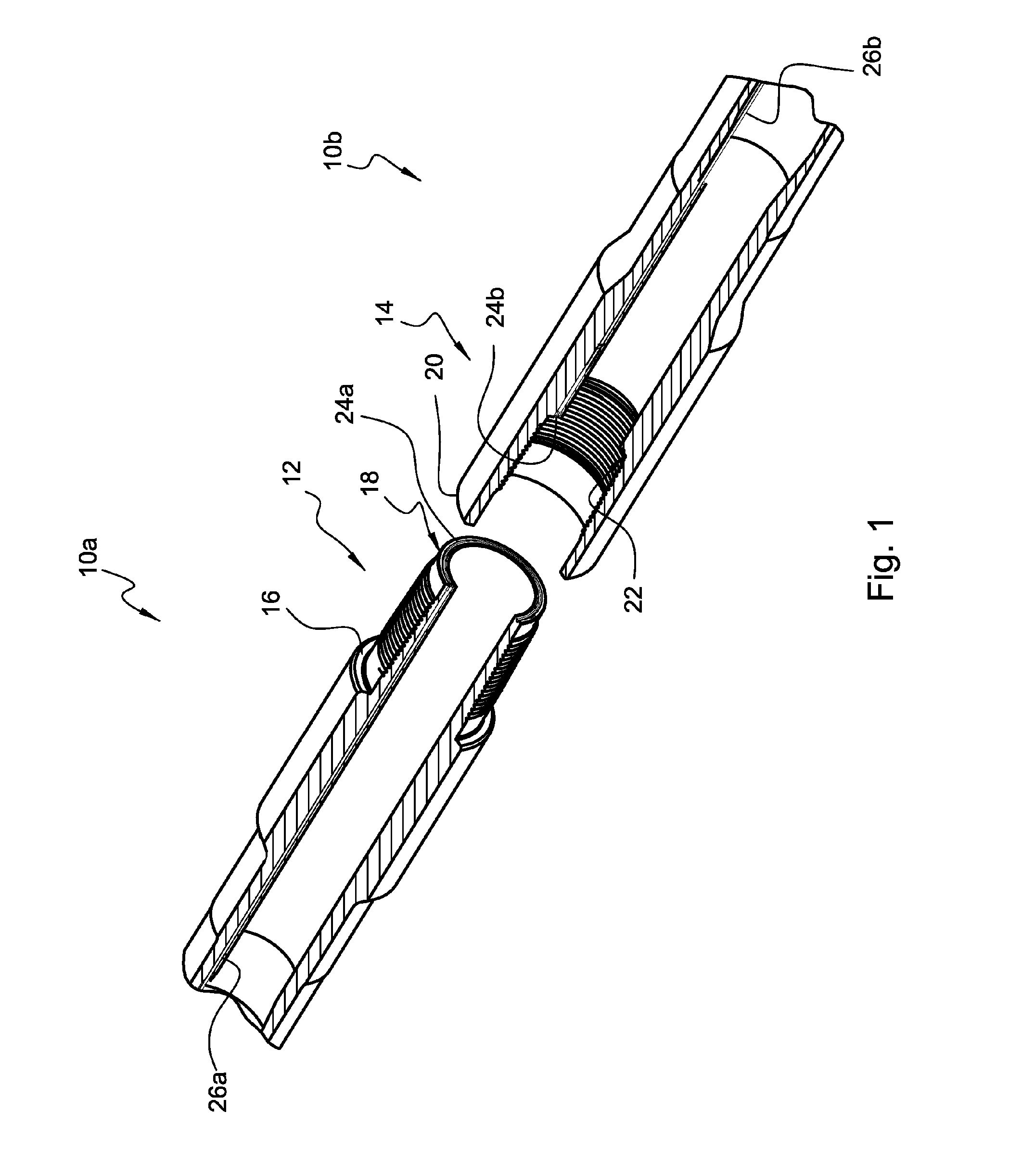
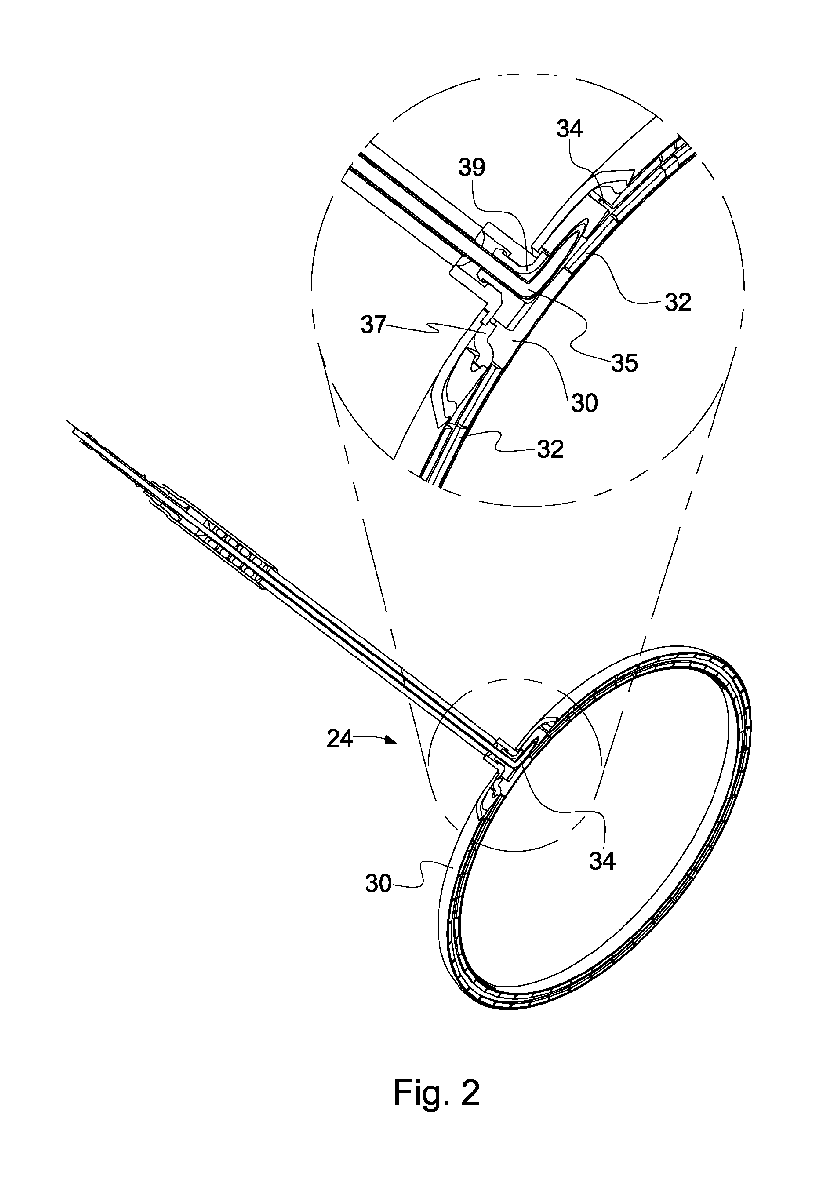
[0029] The illustrated embodiments of the invention will be best understood by reference to the drawings, wherein like parts are designated by like numerals throughout. Furthermore, the described features, structures, or characteristics of the invention may be combined in any suitable manner in one or more embodiments. In the following description, numerous specific details are disclosed to provide a thorough understanding of embodiments of the invention. One skilled in the relevant art will recognize, however, that the invention...


PUM


Abstract

An apparatus in accordance with the invention may include a downhole tool and a data transmission path incorporated into the downhole tool. The data transmission path may include one or more contact surfaces providing electrical continuity to the data transmission path. To protect the contact surfaces from corrosion while maintaining electrical conductivity, a coating may be attached to one or more of the contact surfaces. The coating may include any of various materials that increase the corrosion-resistance of the underlying base metal, including but not limited to cobalt, nickel, tin, tin-lead, platinum, palladium, gold, silver, zinc, or combinations thereof.

Description

CROSS REFERENCE TO RELATED APPLICATIONS [0001] The present invention is a continuation-in-part of U.S. patent application Ser. No. 10 / 604,812 filed Aug. 19, 2003, the entire disclosure of which is incorporated by reference herein. U.S. patent application Ser. No. 10 / 604,812 is a continuation of U.S. patent application Ser. No. 09 / 816,766 filed on Mar. 23, 2001, now U.S. Pat. No. 6,670,880, the entire disclosure of which is incorporated by reference herein. Said application Ser. No. 09 / 816,766 is a continuation-in-part of U.S. patent application Ser. No. 09 / 619,084, filed Jul. 19, 2000, the entire disclosure of which was incorporated by reference in U.S. patent application Ser. No. 09 / 816,766, and the specification and drawing figures of which portions are herein copied.BACKGROUND OF THE INVENTION [0002] The goal of accessing data from a drill string has been expressed for more than half a century. As exploration and drilling technology has improved, this goal has become more importa...

Claims


Application Information

Patent Timeline
Patent Type & Authority Applications(United States)
IPC IPC(8): E21B17/02E21B17/042E21B47/12F16L15/00F16L25/01H01R13/03H01R13/533
CPCE21B17/028E21B17/042E21B47/122E21B47/011F16L25/01H01R13/03H01R13/533F16L15/007E21B47/017E21B47/13E21B17/0285
Inventor HALLDAHLGREN, SCOTT STEVENSMITH, PIERRE A.
Owner INTELLISERV
Why Eureka
Try Eureka