
Transparent electrode for the radiofrequency ablation of tissue

a transparent electrode and radiofrequency ablation technology, applied in the field of human tissue radiofrequency ablation, can solve the problem that the ablative tissue region was sometimes unrecognizable, and achieve the effect of accurate and responsive temperature measurement and more cost-effectiveness

Active Publication Date: 2009-05-05
OLYMPUS CORP
View PDF17 Cites 132 Cited by
  • Summary
  • Abstract
  • Description
  • Claims
  • Application Information

AI Technical Summary

Benefits of technology

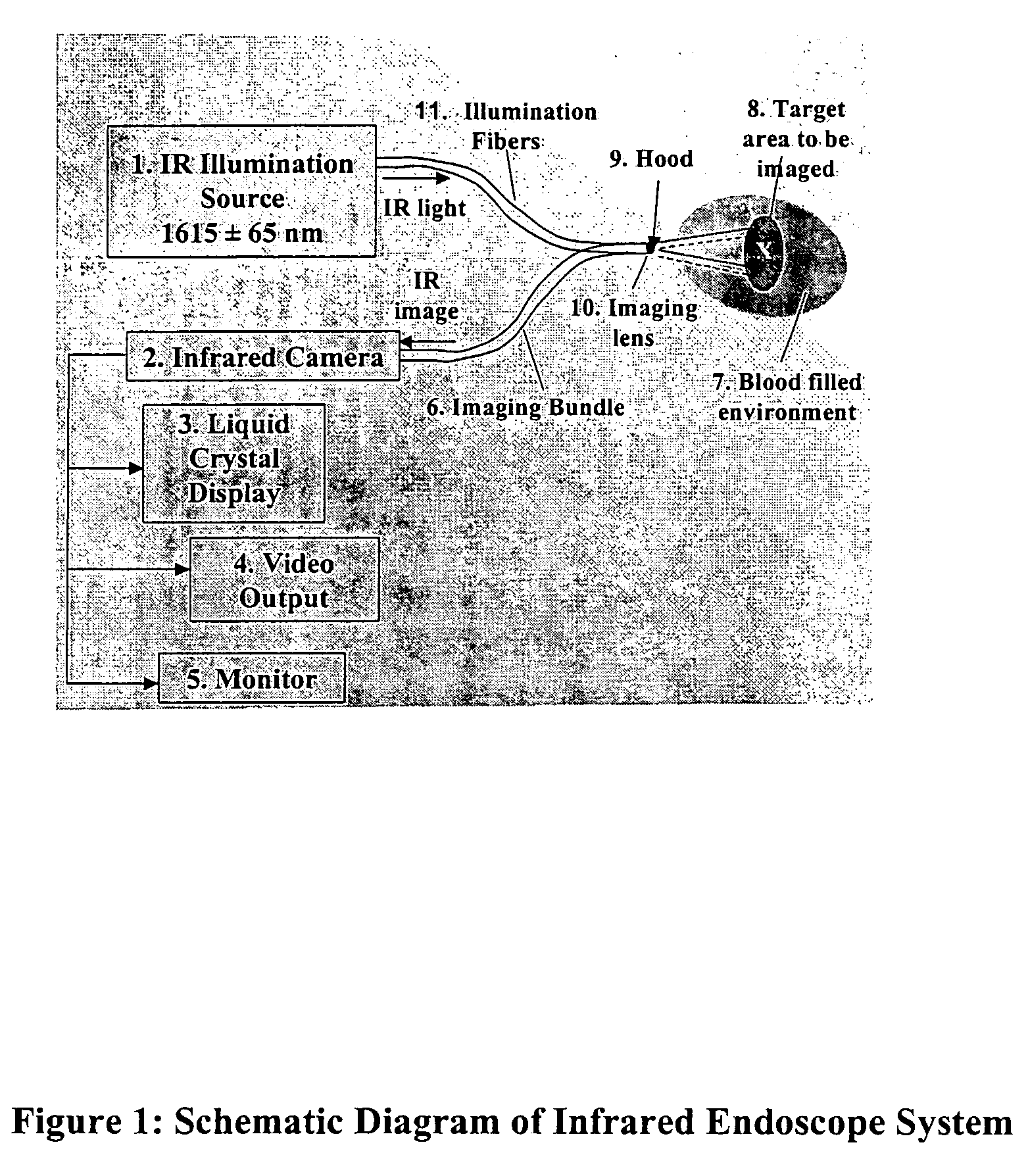
The patent text describes a method for improving the visualization of ablation procedures in the heart by using a transparent ablation electrode and a thin metallic coating on the endoscope. This allows for better imaging of the ablation region and more precise control of the output of the RF generator. The invention also includes methods for constructing complex electrode patterns and thermocouples for more accurate temperature control. The technical effects of this invention include improved visualization of the ablation region, better control of RF generator output, and more accurate temperature control.

Problems solved by technology

This close-proximal positioning of the individual catheters was very time consuming and once achieved, the resulting image contained motion artifact and the ablative tissue region was sometimes unrecognizable due to varying angles and distances between the two catheters.

Method used


Image

  • Transparent electrode for the radiofrequency ablation of tissue
  • Transparent electrode for the radiofrequency ablation of tissue
  • Transparent electrode for the radiofrequency ablation of tissue

Examples


embodiment 1

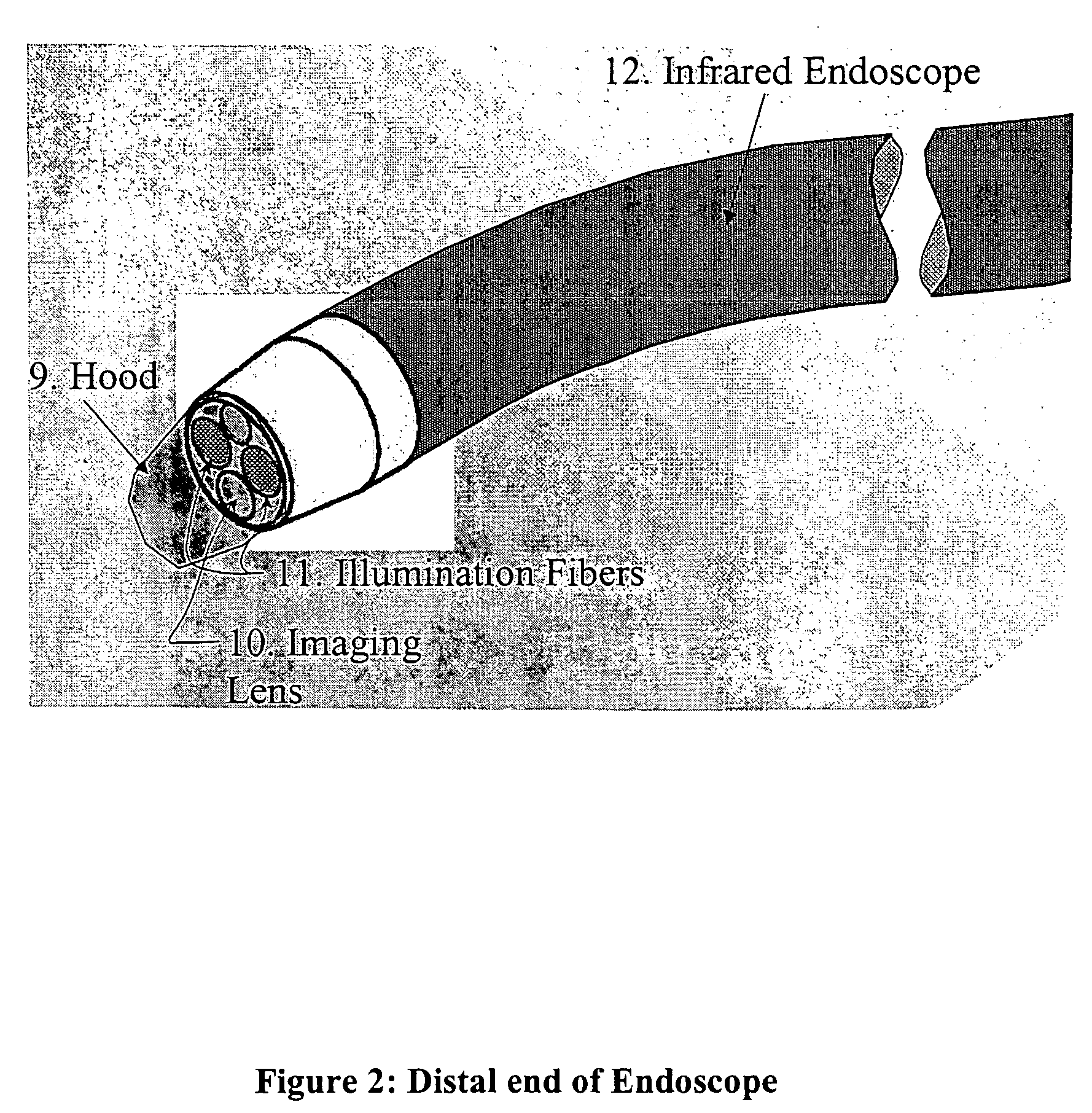
[0077]In FIG. 3, gold is deposited uniformly over the hood at about a 20-80 nm thickness. The gold coating is extended and attached to a gold connecting pad (13). The gold connecting pad is also electrically connected to a nitinol wire (15), which extends out of the proximal end of the catheter and is plugged into an RF generator for catheter ablation procedures. This configuration allows the physician to view the ablative process in real-time through a transparent ablation electrode.

[0078]In addition, the use of minute metallic quantities coupled with a gold, titanium or nitinol connecting wire—all non-magnetic materials—make this catheter magnetic resonance (MR) imaging compatible. Since MR machines utilize powerful magnets, conventional ablation catheters constructed from steel wires and platinum hemispheres are not only moved by the large magnets but can heat tissue from induction by the magnetic fields. With the metal-deposition process, even if a magnetic material is used, the...

embodiment 2

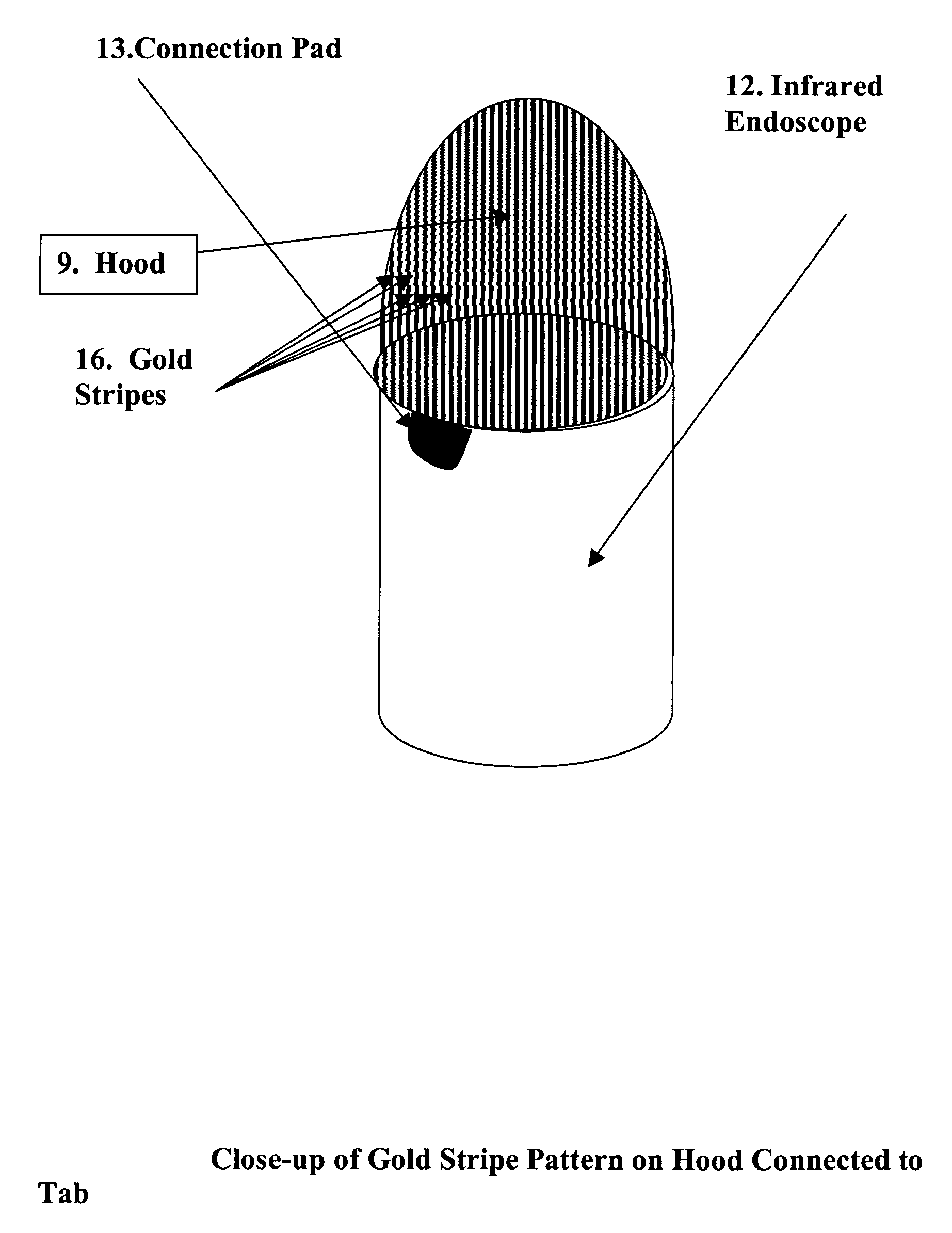
[0079]An alternative to constructing a transparent electrode by coating it with a very thin layer of gold, is to form a pattern on the hood which includes enough space between the gold-deposited pattern so it appears nearly transparent on the viewing monitor. FIG. 4 shows such an embodiment. In this embodiment, a series of gold-plated stripes (16) are fabricated on the surface of the hood. Each of these stripes is connected to a gold connecting pad (13). As shown in FIG. 5, the connecting pad is connected to a nitinol, titanium or gold wire (15) for connection to an RF generator. The gold stripe does need not to be transparent since adequate imaging is provided by the spaces between the stripes. The pattern can be a cross-hatched as well as striped. The spacing between metallic lines should be no greater than one millimeter since RF energy ablates tissue about one millimeter from the electrode surface. Sub-millimeter spacings will insure a continuous lesion in the spaces between ele...

embodiment 3

[0081]A typical application of the invention is with a transvenous catheter, however the invention is not limited to that application. The next embodiment (FIG. 6) depicts a rigid conventional visible-region endoscope (18) ablating a liver tumor (19). As in the infrared endoscope, a glass hood (9) is placed over the proximal end of the endoscope. The hood is coated with a gold coating of about 60 nanometers or less. A nitinol wire connects the gold coating to an RF generator (17). The endoscope provides visual confirmation of the tumor ablation. The demarcation of the tumor boundary to normal tissue is observable in the endoscope image viewed on the monitor. This permits greater precision in eradicating the tumor with safe margins into healthy tissue to assure non-reoccurrence of the tumor.


PUM

PropertyMeasurementUnit
lengthaaaaaaaaaa
diameteraaaaaaaaaa
thicknessaaaaaaaaaa

Abstract

A novel transparent electrode that uses a conductive coating to allow delivery of current to the heart as well as outward imaging through the electrode is described. The embodiments disclose a catheter incorporating an endoscope, whose imaging tip is coated with a conductive coating that is transparent in the endoscopic image. However, a transparent electrode may be fashioned for any imaging modality, such as intracardiac echocardiography (ICE), that finds the electrode to be transparent to the energy used. This electrode coating may be a thin, optically transparent or translucent coating of platinum or gold or may be a pattern with enough open spaces to see the underlying tissue, such as looking through a screen. A wire is connected to the conductive coating and routed to a radiofrequency generator.

Description

BACKGROUND OF THE INVENTION[0001]This invention relates to radiofrequency ablation of human tissue, particularly heart tissue for the elimination of arrhythmias.[0002]The following references provide useful background material to the present invention, and are all incorporated herein by reference.[0003]Patent References:Kushihashi12 / 1969 3,484,263Levy6,19703,515,571Avitall1 / 19965,487,385Swanson12 / 1996 5,582,609Swartz12 / 1998 5,846,223Shearon7 / 19995,919,188Haissauguerre5 / 20006,064,902Amundson1 / 20016,178,346O'Brian1 / 20016,168,825Suorsa3 / 20016,206,831Webster4 / 20016,210,406Tu5 / 20016,238,390Gaiser6 / 20016,241,728Stewart12 / 2001 6,325,797Sutton9 / 20026,443,950Amundson11 / 2002 PCT / US02 / 361;PCT / US02 / 364Other ReferencesKnight5 / 2004Heart Rhythm 2004Abstract 26Lardo et al. “Visualization and Temporal / Spatial Characterization of Cardiac Radiofrequency Ablation Lesions using Magnetic Resonance Imaging” Circ 2000: 102: 698-705[0004]In the field of cardiology, arrhythmias (irregularities in heart rate)...

Claims


Application Information

Patent Timeline
Patent Type & Authority Patents(United States)
IPC IPC(8): A61B18/18
CPCA61B18/1492A61B2017/00907A61B2018/00077A61B2018/00148
Inventor KNIGHT, BRADLEY P.BLANKENSHIP, LARRYHANLIN, JOHN H.AMUNDSON, DAVID C.
Owner OLYMPUS CORP
Learn More