
Method of selecting inks for use in imaging with an imaging apparatus

a technology of imaging apparatus and ink, applied in the field of printing, can solve the problems of serious visual artifacts, poor light fastness, and creation of visual artifacts, and achieve the effects of reducing mottling and smearing, reducing glossy transition artifacts, and increasing the smoothness of color transitions

Inactive Publication Date: 2008-07-22
FUNAI ELECTRIC CO LTD
View PDF18 Cites 2 Cited by
  • Summary
  • Abstract
  • Description
  • Claims
  • Application Information

AI Technical Summary

Benefits of technology

The present invention provides an improved method for selecting inks for use in imaging with an imaging apparatus. This method involves determining the maximum usage of a diluted ink and the saturated ink based on visual perception characteristics, and optimizing the usage of the inks to create a final colorant space. A color conversion lookup table is then generated based on the final colorant space to achieve reduced mottling and smearing in the image, as well as avoidance of paper-cockling and soak-through of the printing substrate. The invention also retains the advantages of using dye-based and pigment-based inks, such as large color gamut, improved light fastness, and good dynamic range of lightness across a range of different print media.

Problems solved by technology

However, visual artifacts, such as mottling and smearing, are created if the diluted inks are not used appropriately.
The dye-based inks have a larger color gamut than pigment-based inks, but poorer light fastness, especially for the diluted inks, whereas the pigment-based inks have a smaller color gamut but much better light fastness.
However, a problem with the hybrid approach is that the gloss transition between the pigment-based inks and the dye-based inks on glossy paper results in serious visual artifacts.

Method used


Image

  • Method of selecting inks for use in imaging with an imaging apparatus
  • Method of selecting inks for use in imaging with an imaging apparatus
  • Method of selecting inks for use in imaging with an imaging apparatus

Examples


Embodiment Construction

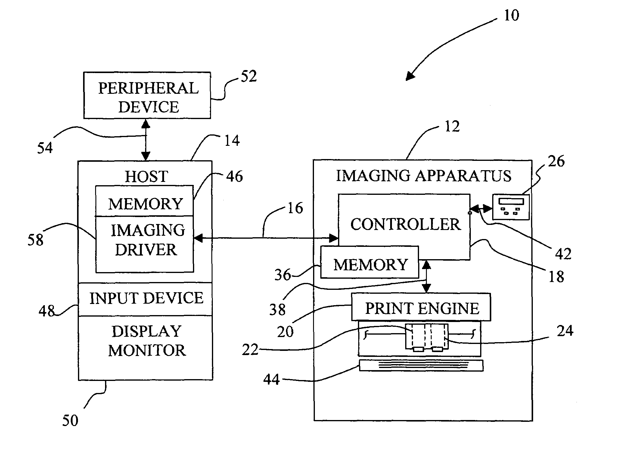
[0031]Referring now to the drawings, and particularly to FIG. 1, there is shown a diagrammatic depiction of an imaging system 10 embodying the present invention. Imaging system 10 includes an imaging apparatus 12 and a host 14. Imaging apparatus 12 communicates with host 14 via a communications link 16.

[0032]Imaging apparatus 12 may be, for example, an ink jet printer and / or copier, or an all-in-one (AIO) unit that includes an inkjet printer, a scanner, and possibly a fax unit. In the present embodiment, imaging apparatus 12 includes a controller 18, a print engine 20, a color printing cartridge 22, a photo printing cartridge 24, and a user interface 26.

[0033]Controller 18 includes a processor unit and associated memory 36, and may be formed as one or more Application Specific Integrated Circuits (ASIC). Controller 18 is a printer controller, but may alternatively be a scanner controller, or combined printer and scanner controller. Although controller 18 is depicted in imaging appar...


PUM


Abstract

A method of selecting inks for use in imaging with an imaging apparatus includes determining a maximum usage of a diluted ink for use in conjunction with a saturated ink based on visual perception characteristics relating to a combination of the diluted ink and the saturated ink; generating an initial colorant space based on the maximum usage of the diluted ink, the initial colorant space expressing an initial usage of the diluted ink and an initial usage of the saturated ink at each point in the initial colorant space; optimizing the initial usage of the diluted ink and the initial usage of the saturated ink in the initial colorant space to generate a final usage of the diluted ink and a final usage of the saturated ink in a final colorant space; and generating a color conversion lookup table based on the final colorant space.

Description

BACKGROUND OF THE INVENTION[0001]1. Field of the Invention[0002]The present invention relates to printing, and, more particularly, to a method of selecting inks for use in imaging with an imaging apparatus.[0003]2. Description of the Related Art[0004]In recent years many inkjet printers with multilevel color inks, sometimes referred to as “photo printers,” have been developed for home and office use. These printers typically perform six-color printing, and employ saturated cyan, saturated magenta, saturated yellow, saturated black, diluted cyan, and diluted magenta inks (CMYKcm). The photo printer cartridges are generally organized in such a way that the saturated cyan, magenta, and yellow inks are in one cartridge, referred to as a “color cartridge,” and the diluted cyan, diluted magenta, and saturated black are in another cartridge, referred to as a “photo cartridge.” The use of diluted inks helps to improve image quality so as to achieve photo-quality images. However, visual arti...

Claims


Application Information

Patent Timeline
Patent Type & Authority Patents(United States)
IPC IPC(8): G06K1/00B41J2/21G06K15/00B41J29/393G01D15/16
CPCB41J2/2107G03G15/104G03G15/0121
Inventor HUANG, XUAN-CHAONYSTROM, BRANT DENNISREEL, RICHARD LEEHOLIWAY, JAMEE CASTEEL
Owner FUNAI ELECTRIC CO LTD
Learn More