Eureka AIR delivers breakthrough ideas for toughest innovation challenges, trusted by R&D personnel around the world.

Structure for attaching stereoscopic camera in vehicle

a technology for stereoscopic cameras and structures, which is applied in the field of structures for attaching stereoscopic cameras to vehicles, can solve the problems of further increase in difficulty in suppressing looseness and shaking of cameras, etc., and achieve the effect of preventing the optical axes of cameras from deviating and a large deformation load

Inactive Publication Date: 2008-07-22
HONDA MOTOR CO LTD
View PDF9 Cites 5 Cited by
  • Summary
  • Abstract
  • Description
  • Claims
  • Application Information

AI Technical Summary

Benefits of technology

[0009]The present invention provides a structure for attaching a stereoscopic camera system to a vehicle which is capable of preventing looseness and shaking of cameras, securely preventing the optical axes of the cameras from deviating as a result of distortion, etc., of the vehicle body, and improving the accuracy when stereoscopically recognizing the surrounding environment.
[0011]According to the invention, since a plurality of points of the lateral stay, or respective cameras fixed on the lateral stay, are fixed on a body frame via the brackets, looseness and shaking of the cameras can be prevented. Also, even if distortion and deformation are brought about on the body frame that supports the lateral stay, the bracket, whose bending rigidity is lower, is deformed prior to the lateral stay, whose bending rigidity is higher, based on operating loads resulting from the distortion and deformation thereof. Moreover, no large load is applied to the lateral stay, wherein it is possible to prevent the optical axes of the cameras from deviating.
[0015]According to the invention, since the reinforcement bead is provided, the rigidity of the bracket can be adjusted. The rigidity of the bracket can be easily adjusted by varying the length, width, and depth of the reinforcement bead. Since the bead can be provided by very simple work, it is possible to quickly adjust the rigidity of the bracket. Further, since different rigidity can be given to the same bracket by varying the length, width and depth of the reinforcement bead, the same bracket is applicable to vehicles whose specifications differ from each other.
[0017]Since the focusing distance of the infrared camera is long, it is necessary to space two cameras from each other by lengthening the lateral stay in order to form the image of a near object on the pickup surface of the cameras. According to the invention, since even a long lateral stay can be firmly fixed on the vehicle body, looseness and shaking of the cameras can be prevented from occurring.
[0019]If the side frame is deformed so as to open sideward by being heated by heat from the engine, the bent portions, formed at both ends of the cross member, are deformed so as to open both ends of the cross member. As a result there is a possibility that a large deformation load operates on the brackets which support the lateral stay. In such a case, according to the invention, the lateral stay is not deformed, but the bracket is deformed. Since no large load is input into the lateral stay, it is possible to prevent the optical axes of the cameras from deviating.

Problems solved by technology

However, since, with the above-described attaching structure, two cameras, which are heavy devices, are supported on the vehicle only at the middle part of the lateral stay, it is difficult to suppress looseness and shaking of the cameras.
In particular, when there is no way other than disposing both the cameras with a spacing secured therebetween in order to secure focal distances of the cameras (in this case, it is necessary to lengthen the lateral stay) and when cameras are installed at the front side of a vehicle subjected to large vibrations, there is a concern that looseness and shaking of the cameras are further increased.

Method used


Image

  • Structure for attaching stereoscopic camera in vehicle
  • Structure for attaching stereoscopic camera in vehicle
  • Structure for attaching stereoscopic camera in vehicle

Examples


Embodiment Construction

[0027]Hereinafter, a description is given of one embodiment of the invention with reference to the drawings.

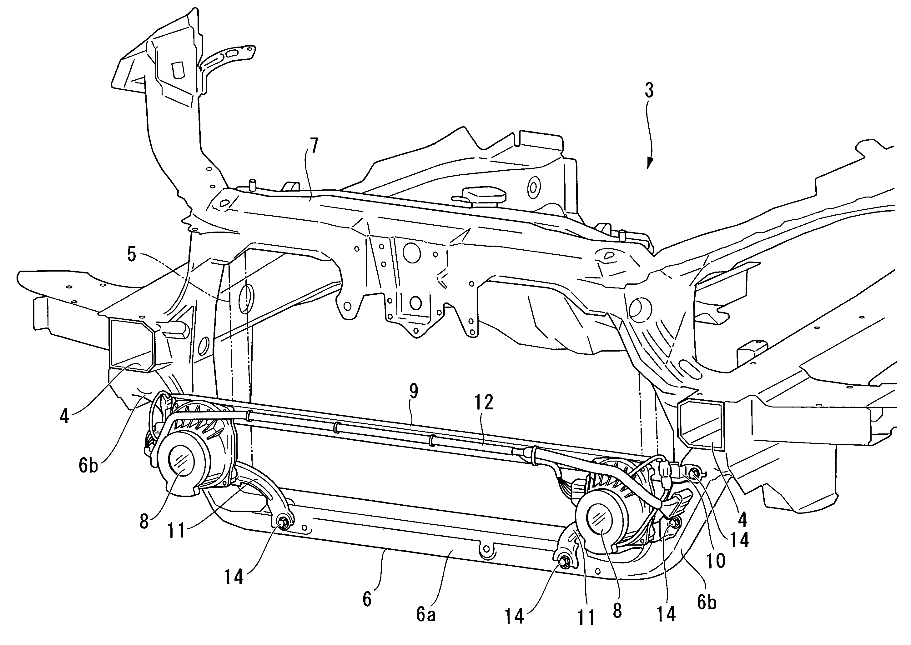
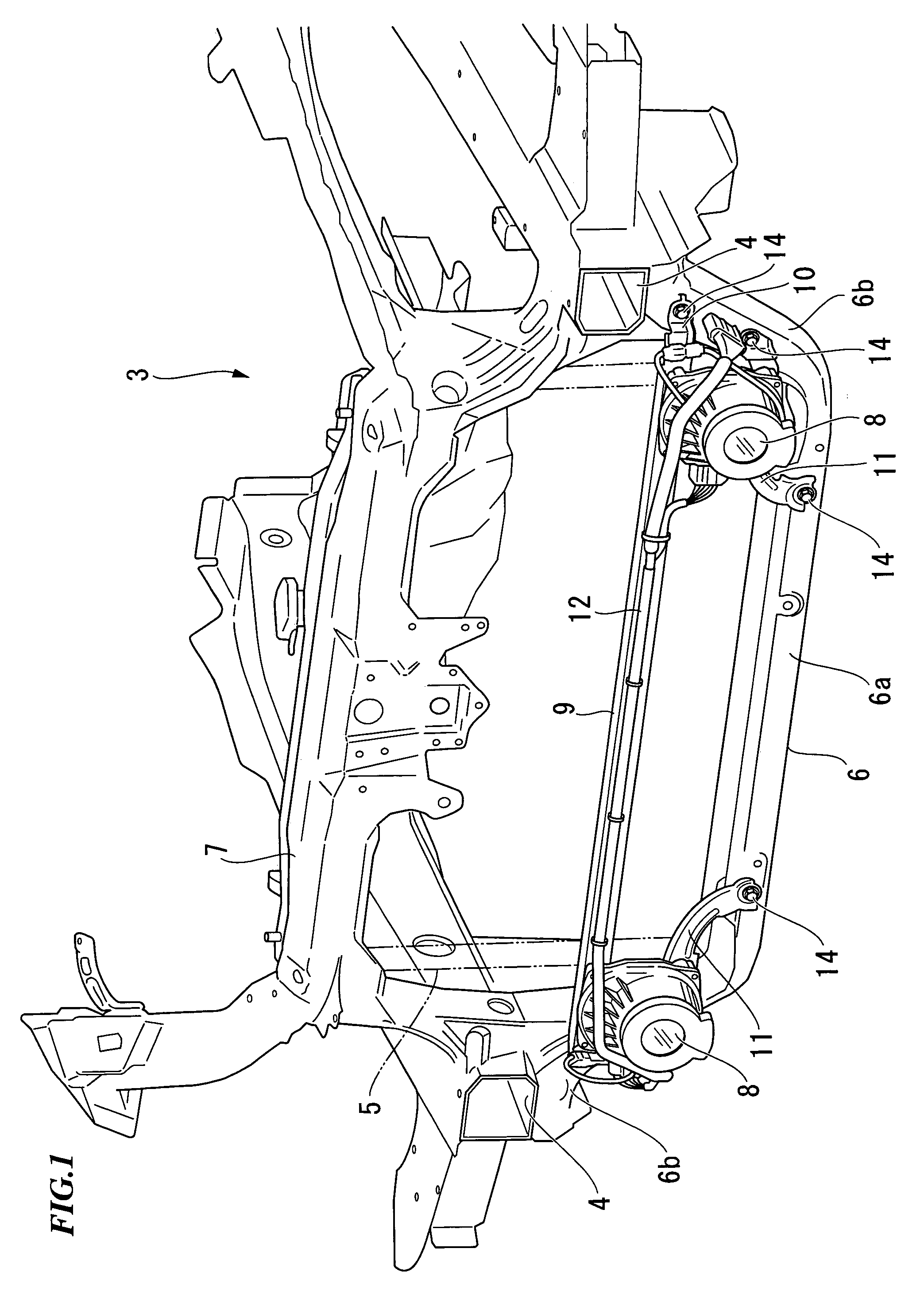
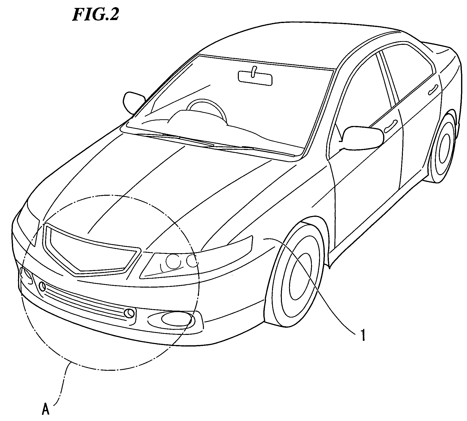
[0028]FIG. 1 is a perspective view of the front end of a vehicle in which the framework of a vehicle body is exposed with the body panels and bumper, etc., removed (the front part A of a vehicle 1 shown in FIG. 2), FIG. 3 is a brief plan view of the same framework, FIG. 4 is a brief front view of the same framework, and FIG. 5 is a brief side view of the same framework. In the drawings, reference numeral 2 denotes an engine, 4 denotes side frames, and 5 denotes a radiator. The side frames 4 are composed as a pair and extend in the longitudinal direction of the vehicle body at both sides of the engine room 3. The radiator 5 cools down the engine coolant.

[0029]The front end part of one side frame 4 is linked with the front end part of the other side frame 4 by a bulkhead lower cross member 6 (the cross member that composes the invention, and hereinafter called a “lower cross mem...


PUM


Abstract

A structure for attaching a stereoscopic camera to a vehicle, by which a plurality of cameras are attached to a body frame of the vehicle in order to stereoscopically capture images surrounding the vehicle; and the same structure includes a lateral stay for coupling the plurality of cameras with each other; and brackets for fixing the lateral stay or the plurality of cameras on the body frame, which are provided at a plurality of points, spaced from each other, of the lateral stay, or at the plurality of cameras fixed on the lateral stay; wherein the rigidity of at least a part of the brackets is lower than the bending rigidity of the lateral stay.

Description

CROSS-REFERENCE TO RELATED APPLICATIONS[0001]The present invention claims priority under 35 USC 119 based on Japanese patent application No. 2004-293576, filed Oct. 6, 2004, the content of which, including written description, claims, and drawings, is incorporated by reference herein.BACKGROUND OF THE INVENTION[0002]1. Field of the Invention[0003]The present invention relates to a structure for mounting a camera to a vehicle, and in particular it relates to a structure for attaching a stereoscopic camera system for a vehicle by which a plurality of cameras are attached to a body frame of the vehicle in order to stereoscopically capture images of the area surrounding the vehicle.[0004]2. Description of Related Art[0005]A technology has been developed, which captures the images of an area surrounding a vehicle while the vehicle is running and when it stops, and the technology utilizes the image information for traveling Support, etc. As one of the representative technologies, a stereo...

Claims


Application Information

Patent Timeline
Patent Type & Authority Patents(United States)
IPC IPC(8): G03B35/00G03B29/00G03B35/18
CPCB60R11/04G03B29/00B60R2011/0038
Inventor MIYAZAKI, YASUAKIHATTORI, HIROSHIWATANABE, MASAHITONAGAOKA, NOBUHARUKATASHIMA, YOSHITAKA
Owner HONDA MOTOR CO LTD
Why Eureka
Eureka Blog
Learn More