Sensor assembly, transformers and methods of manufacture

a transformer and sensor technology, applied in the field of sensors, can solve the problems of signal conditioning adding complexity and cost to the system design, reducing the sensitivity and accuracy of the probe,

Active Publication Date: 2008-07-29
GENERAL ELECTRIC CO
View PDF13 Cites 11 Cited by
  • Summary
  • Abstract
  • Description
  • Claims
  • Application Information

AI Technical Summary

Problems solved by technology

The variation in the properties of the cable may produce substantially large noise components in the signal thereby reducing the sensitivity and accuracy of the probes.
However, the electronic signal conditioning adds complexity and cost to the system design.

Method used


Image

  • Sensor assembly, transformers and methods of manufacture
  • Sensor assembly, transformers and methods of manufacture
  • Sensor assembly, transformers and methods of manufacture

Examples


Embodiment Construction

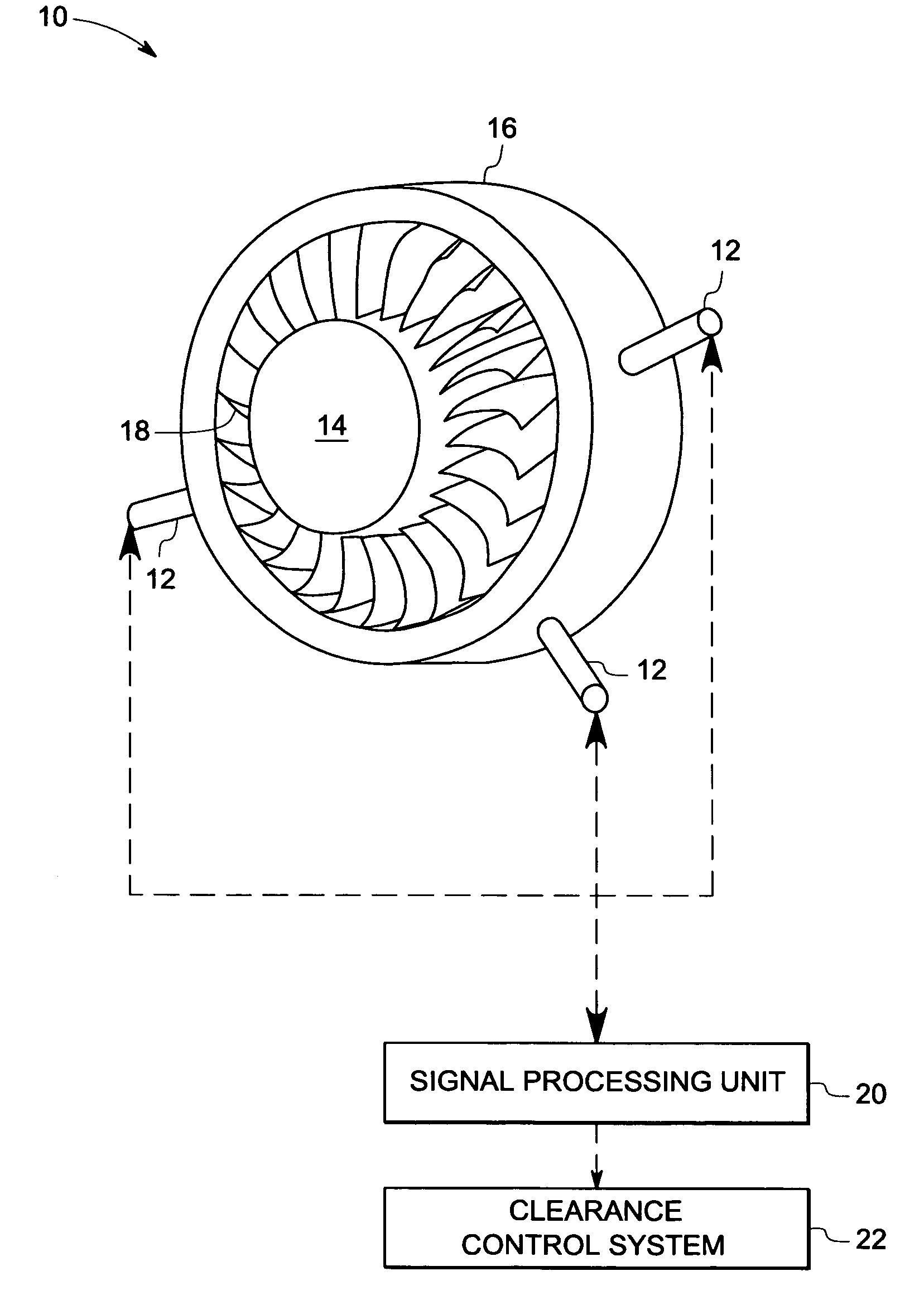
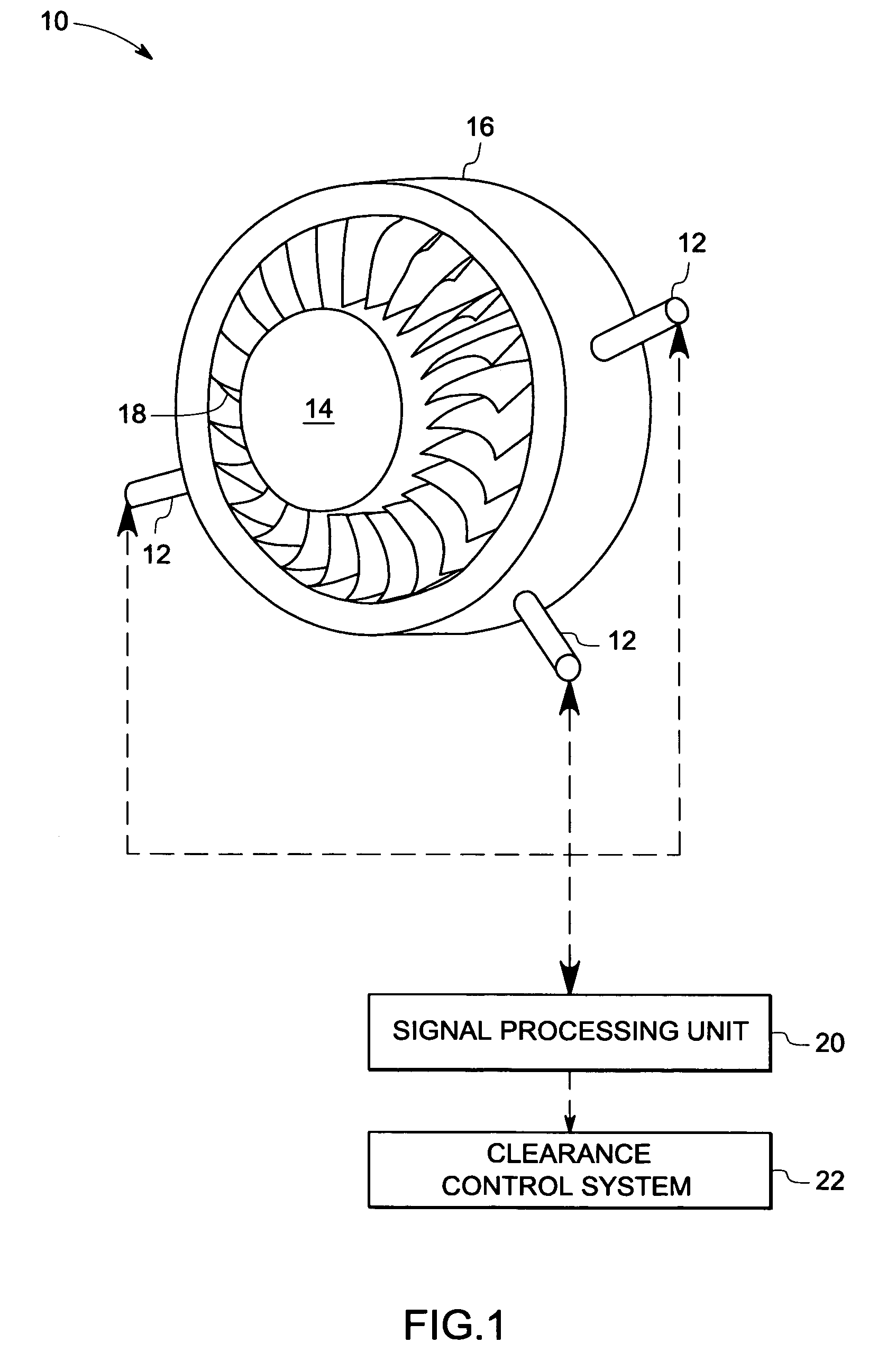
[0016]As discussed in detail below, embodiments of the present invention function to provide a sensor that provides an accurate measurement of a sensed parameter in high temperature environments. In particular, the present invention provides a sensor that detects a value of a physical property from a value in impedance. For example, the sensor may be employed to measure a capacitance value between the sensor and an external object that is representative of clearance between the sensor and the external object in various systems such as a steam turbine, a generator, a turbine engine, a machine having rotating components, and so forth.

[0017]Referring now to the drawings, FIG. 1 illustrates a turbine 10 of an engine having a sensor assembly 12 in accordance with an exemplary embodiment of the present invention. The turbine 10 includes a rotor 14 disposed within a casing 16. Further, the rotor 14 includes a number of turbine blades 18 disposed within the casing 16. In this exemplary embo...


PUM

PropertyMeasurementUnit
widthaaaaaaaaaa
widthaaaaaaaaaa
widthaaaaaaaaaa

Abstract

A sensor assembly is provided. The sensor assembly includes a sensor configured to measure an impedance value representative of a sensed parameter and a transformer coupled to the sensor. The transformer includes at least one ceramic substrate and at least one electrically conductive line disposed on the ceramic substrate to form at least one winding. The electrically conductive line includes an electrically conductive material.

Description

BACKGROUND[0001]The invention relates generally to sensors and, more particularly, to a sensor assembly that is configured to provide an accurate measurement of a sensed parameter in a high temperature environment.[0002]Various types of sensors have been used to measure the distance between objects. In addition, such sensors have been used in various applications. For example, in turbine systems, the clearance between a static shroud and turbine blades is greatest when the turbine is cold, and gradually decreases as the turbine heats up and as it spins up to speed. It is desirable that a gap or clearance between the turbine blades and the shroud be maintained for safe and effective operation of the turbine. A sensor may be disposed within the turbine to measure the distance between the turbine blades and the shroud. The distance may be used to direct movement of the shroud to maintain the desired displacement between the shroud and the turbine blades.[0003]In certain applications, c...

Claims


Application Information

Patent Timeline
Patent Type & Authority Patents(United States)
IPC IPC(8): G01L9/10
CPCH01F17/0006H01F41/041H01F27/2804H01F17/03H01F17/0013
Inventor RUUD, JAMES ANTHONYANDARAWIS, EMAD ANDARAWISDASGUPTA, SAMHITASHAH, MINESH ASHOKBALASUBRAMANIAM, MAHADEVAN
Owner GENERAL ELECTRIC CO
Why Eureka
Try Eureka