Gauge pointer and light guide structure

a technology of light guide structure and pointer, which is applied in the direction of instruments, measurement device, measurement apparatus components, etc., can solve the problems of light not being able to be directed onto light not being able to pass to a second gauge face in front of the pointer, and each has its own limitations

Inactive Publication Date: 2008-07-29
DENSO INTERNATIONAL AMERICA
View PDF33 Cites 19 Cited by
  • Summary
  • Abstract
  • Description
  • Claims
  • Application Information

AI Technical Summary

Problems solved by technology

While current vehicle gauges have generally proven to be satisfactory for their applications, each is associated with its share of limitations.
One limitation of current gauges is that light can not be directed onto a second gauge face in front of the pointer using a light source behind the pointer.
Another limitation of current gauges is that light can not be passed to a second gauge face in front of the pointer using current gauge structures, such as a single PCB.
Still yet another limitation is that projecting light to a gauge face in front of a pointer traditionally requires wiring or electrical leads in front of the pointer, which may limit gauge function, such as pointer rotation sweep angle.
Finally, current pointers do not permit light to pass through their thicknesses, so that such light may be further used in other areas of the gauge.

Method used


Image

  • Gauge pointer and light guide structure
  • Gauge pointer and light guide structure
  • Gauge pointer and light guide structure

Examples


Embodiment Construction

[0015]The following description is merely exemplary in nature and is not intended to limit the present disclosure, application, or uses. Throughout the drawings, corresponding reference numerals indicate like or corresponding parts and features.

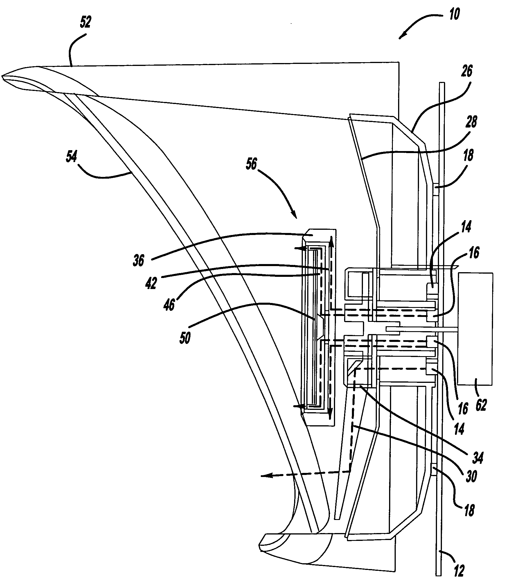
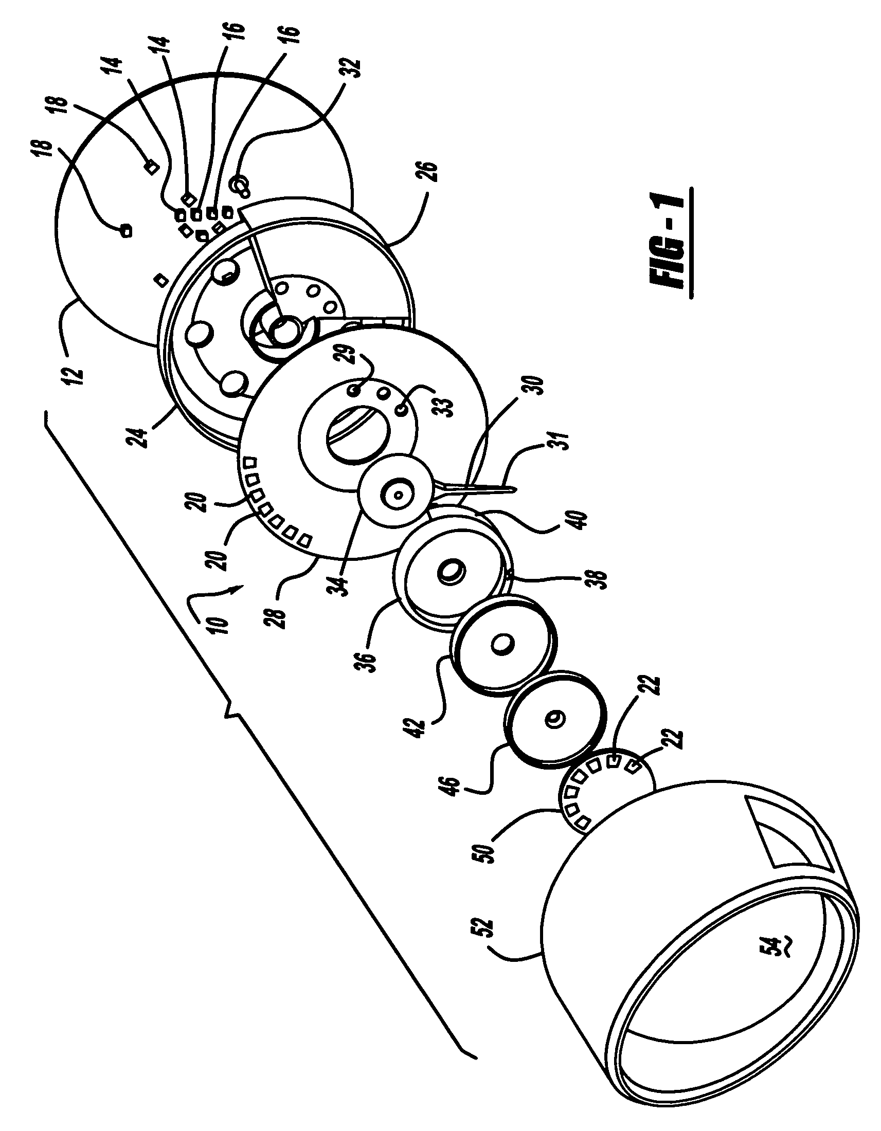
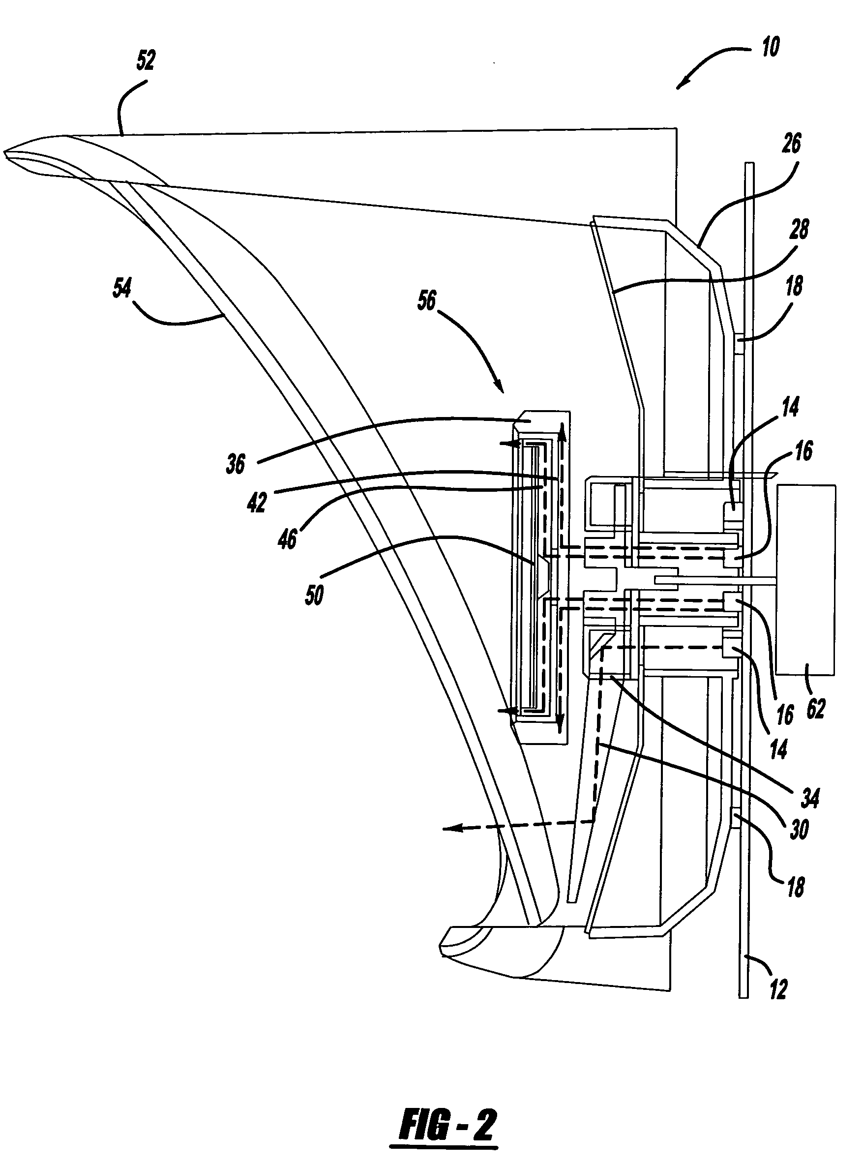
[0016]Turning now to FIG. 1, an exploded view of a gauge 10 is depicted. More specifically, the gauge 10 is an assembly of various parts such as, but not limited to, a printed circuit board 12 (“PCB”) and groupings of light emitting diodes 14, 16, 18 (“LED”). A first plurality of light emitting diodes 14, a second plurality of light emitting diodes 16, and a third plurality light emitting diodes 18 provide the necessary light to the rear indicia 20 and front indicia 22. The rear indicia 20 may represent vehicle speeds measured in miles per hour (MPH), as on a speedometer, that a vehicle may undergo as it is driven. As a second, separate scale, the front indicia 22 may represent a different vehicle speed scale, such as kilometers per hour (KPH...


PUM


Abstract

A gauge with indicating pointer has three light sources on a printed circuit board. A rear dial plate has rear markings such as MPH indicia. The first light source illuminates the pointer length, which points to the rear indicia. The second light source illuminates a front dial assembly located on an opposite side of the indicator as the rear dial plate by passing light through the thickness of the indicator. The front dial assembly is cantilevered over the rotating pointer to permit pointer rotation. The third light source illuminates the rear indicia. The front dial assembly has a front dial plate with front indicia illuminated by the second light source and to which the pointer points. The three light sources may be different colors since each illuminates a specific area of the gauge. The front dial assembly may display a separate lighted scale, such as KPH from the rear markings.

Description

FIELD[0001]The present disclosure relates to a vehicle gauge and light guide structure. More specifically, the disclosure relates to a light guide structure with an indicator that is capable of passing light through its thickness to provide light to a dial in front of the pointer.BACKGROUND[0002]The statements in this section merely provide background information related to the present disclosure and may not constitute prior art. A conventional vehicle gauge, such as a speedometer gauge, typically has a light source positioned on a printed circuit board (“PCB”) to direct light to the gauge face or through the gauge face to make any indicia, such as numbers, visible to a person viewing the gauge. Additionally, gauges known in the art may have a pointer that is illuminated when light is directed through the pointer length from one end of the pointer.[0003]While current vehicle gauges have generally proven to be satisfactory for their applications, each is associated with its share of ...

Claims


Application Information

Patent Timeline
Patent Type & Authority Patents(United States)
IPC IPC(8): G01D11/28G12B11/02
CPCG01D13/265G01D11/28B60K2370/336B60K2370/698B60K2370/6992Y10S116/36
Inventor KATO, TAKAHIRA
Owner DENSO INTERNATIONAL AMERICA
Why Eureka
Try Eureka