
Direct injection internal combustion engine

a technology of internal combustion engine and injection chamber, which is applied in the direction of machines/engines, fuel injection pumps, output power, etc., can solve the problems of reducing fuel efficiency and knocking in this area, and achieve the effect of reducing the likelihood of knocking, reducing the compression ratio, and increasing the compression ratio

Inactive Publication Date: 2008-07-29
YAMAHA MOTOR CO LTD
View PDF27 Cites 3 Cited by
  • Summary
  • Abstract
  • Description
  • Claims
  • Application Information

AI Technical Summary

Benefits of technology

The present invention provides an internal combustion engine with a high compression ratio and improved operation and fuel efficiency even when the air-fuel ratio is lean. This is achieved by enriching the air-fuel mixture in the peripheral area around the spark plug, which helps to reduce knocking and improve ignition. The engine also includes a fuel injection valve that injects fuel during the intake stroke and a spark plug that creates a generally stratified air-fuel charge. These technical features can lead to reduced fuel consumption and improved performance even at high load operations.

Problems solved by technology

As a result, it takes time until ignition occurs by the flame propagating through the air-fuel mixture in the peripheral area, which can cause knocking in this area.
Thus, one technique to reduce the likelihood of knocking is reducing the compression ratio; however, reduced compression ratios result in decreased fuel efficiency.

Method used


Image

  • Direct injection internal combustion engine
  • Direct injection internal combustion engine
  • Direct injection internal combustion engine

Examples


Embodiment Construction

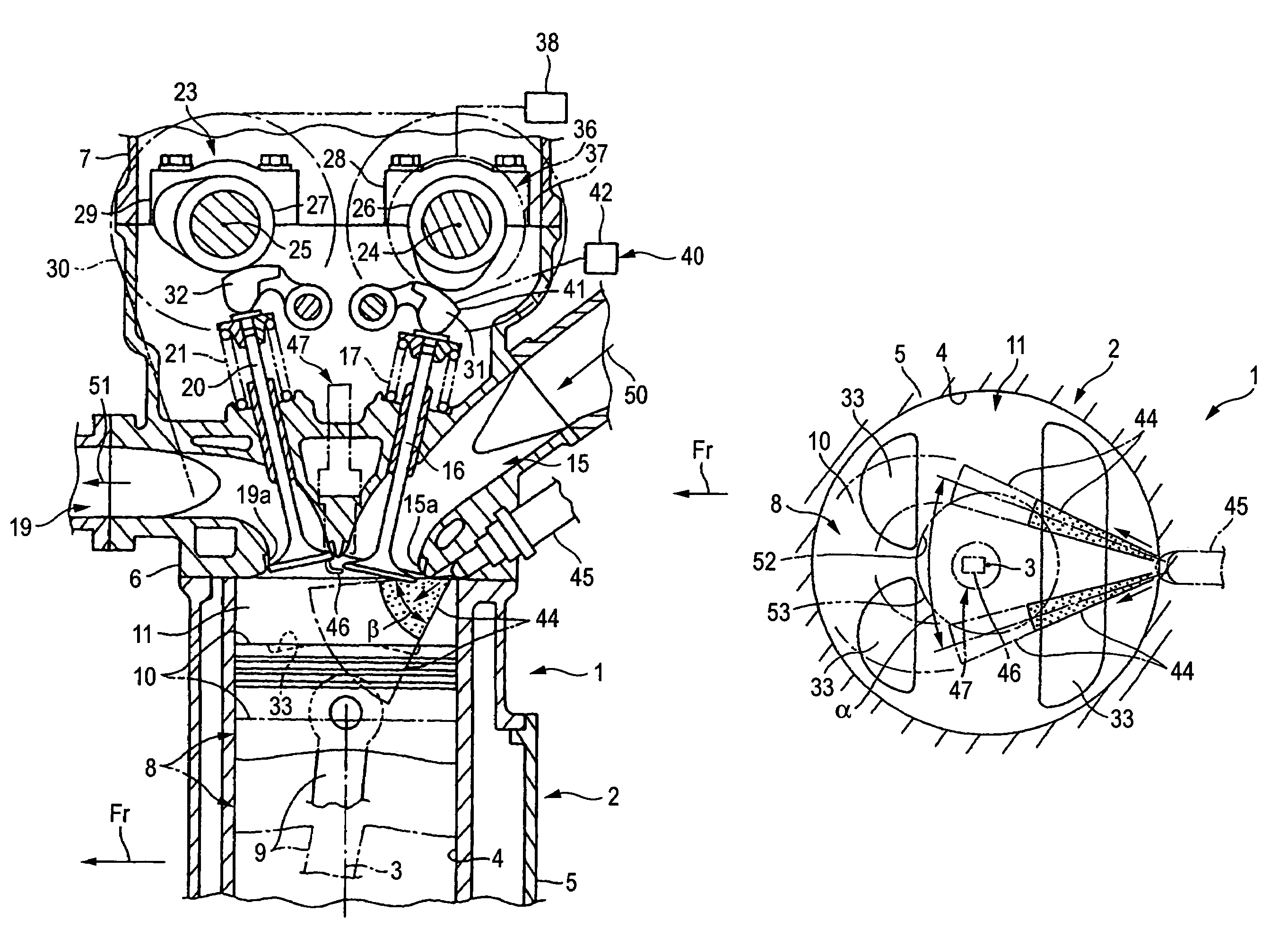
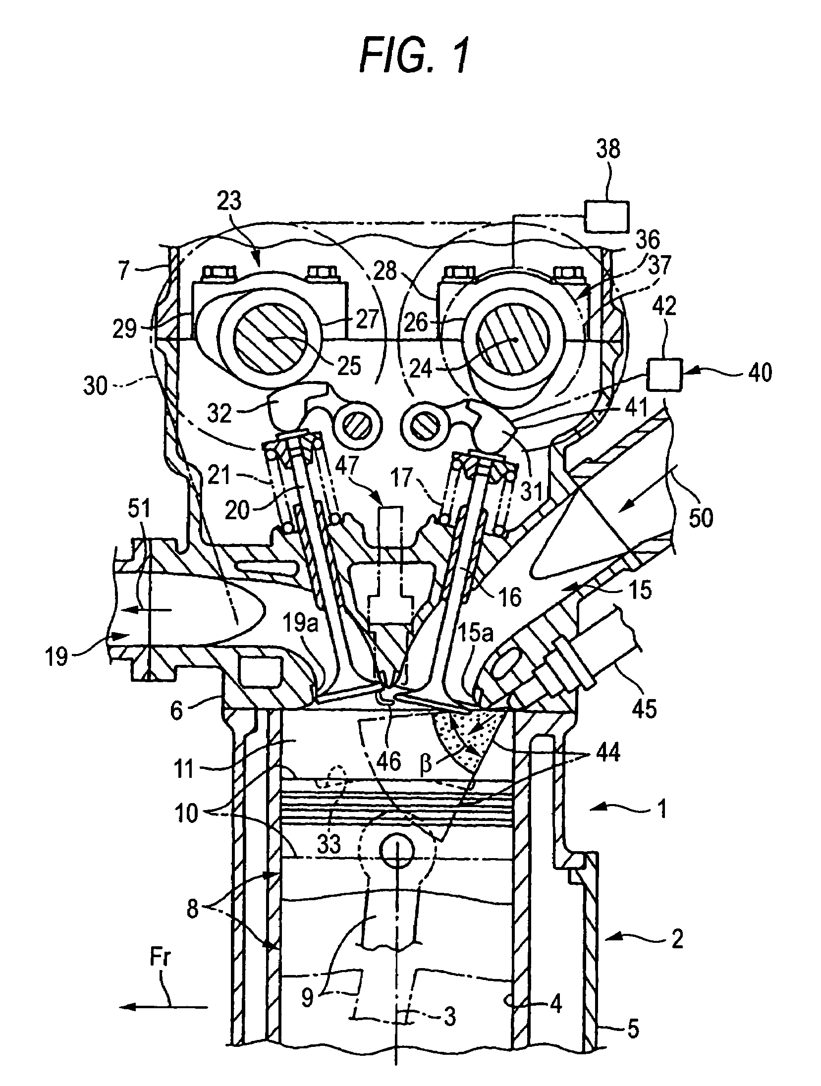
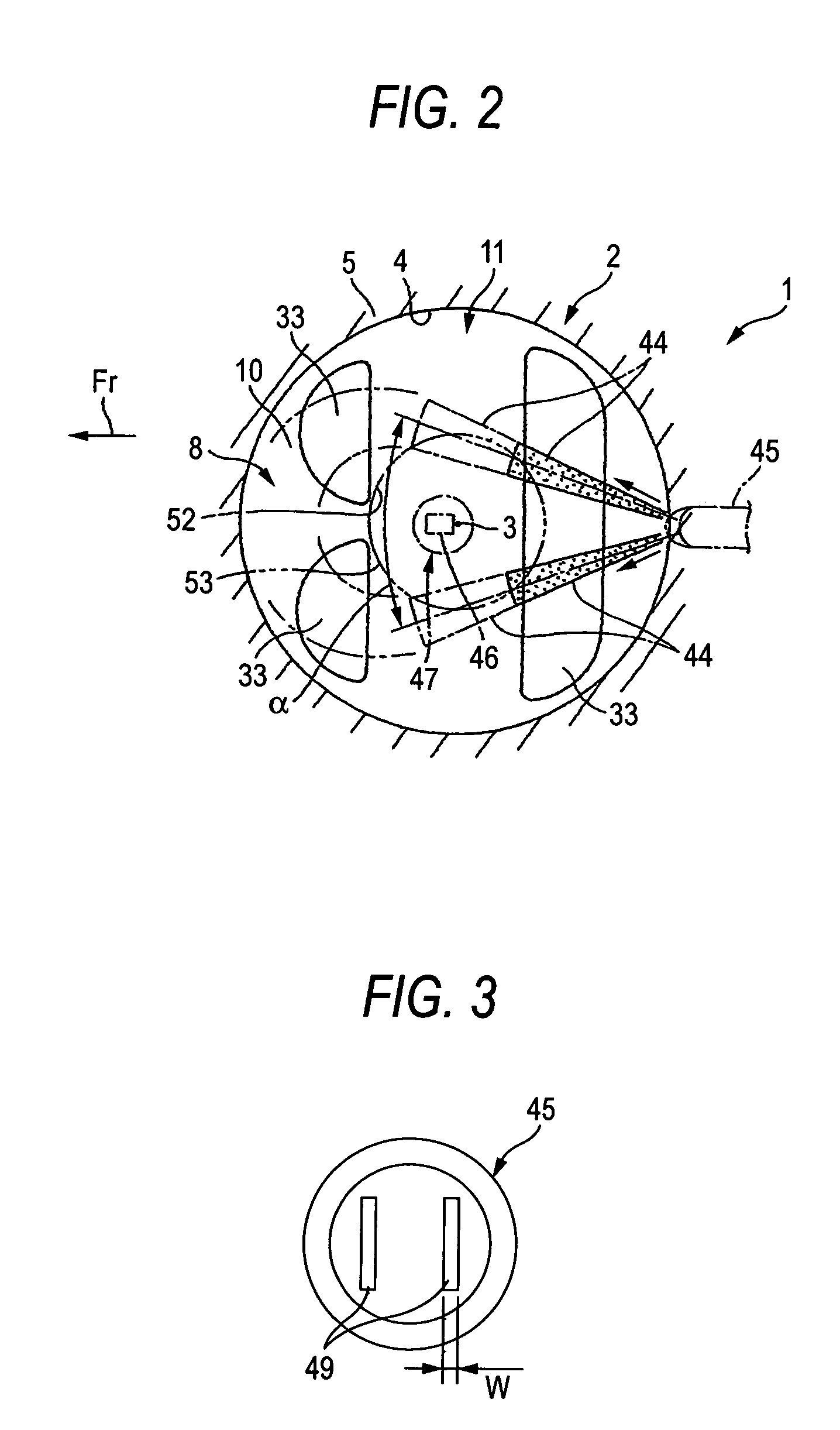
[0018]With reference initially to FIG. 1, an internal combustion engine 1 is shown. The engine 1 can be mounted on a vehicle, such as a motorcycle, an automobile, a watercraft or the like. Preferably, the internal combustion engine 1 is a multi-cylinder, four-stroke engine. The engine 1 can have any number of cylinders and configurations (e.g., inline, V, etc.). Moreover, the cylinders can be vertically arranged, inclined or the like.

[0019]A portion of a vehicle body, frame or the like preferably supports a crankcase of the internal combustion engine 1. The crankcase houses and supports a crankshaft (not shown) in any suitable manner. The crankcase defines a portion of an engine block and the engine block defines one or more cylinders 2 that generally extend away from the portion of the crankcase that would house the crankshaft.

[0020]A cylinder body 5 defines a cylinder bore 4 for each of the cylinders 2. Each cylinder bore 4 preferably extends away from the crankcase and comprises ...


PUM


Abstract

A direct injection engine has a fuel injection valve that directs a spray of fuel to each side of a spark plug electrode. The fuel mixes with the air to define a region of relatively richer air-fuel mixture and a region of relatively leaner air-fuel mixture. The electrode is positioned within the relatively leaner region.

Description

RELATED APPLICATIONS[0001]This application is a continuation of PCT Application No. PCT / JP03 / 02392, filed on Feb. 28, 2003, which claims priority to Japanese Patent Application No. 2002-054358, filed on Feb. 28, 2002, and both applications are hereby incorporated by reference in their entirety.BACKGROUND OF THE INVENTION[0002]1. Field of the Invention[0003]The present invention generally relates to a direct injection internal combustion engine and more particularly relates to such an engine in which the fuel is supplied in a stratified manner with a lean mixture proximate a spark plug electrode and a rich mixture proximate a cylinder wall.[0004]2. Description of the Related Art[0005]Japanese Patent Application No JP-A-2000-345944 disclosed a direct injected internal combustion engine. The engine comprised a cylinder bore and a cylinder head. A piston was positioned in the cylinder bore and reciprocated therein. The cylinder head had an intake passage in one side portion and an exhau...

Claims


Application Information

Patent Timeline
Patent Type & Authority Patents(United States)
IPC IPC(8): F02B3/02F01L1/053F01L1/18F01L1/34F02B17/00F02B23/10F02B75/12F02D13/02F02M61/14F02M61/18F02M69/04
CPCF01L1/0532F01L1/34F02B17/005F02B23/104F02B23/105F02D13/0207F02M61/184F02M69/045F01L1/18Y02T10/123F01L2001/0537F01L2800/00F01L2800/12F02B2023/103F02B2023/106F02B2075/125Y02T10/12Y02T10/125Y02T10/18F01L13/00F02M61/14F02M61/18
Inventor TANAKA, DAIJIROSUZUKI, YUICHI
Owner YAMAHA MOTOR CO LTD
Learn More