Ball-and-socket joint with an angle sensor

a technology of angle sensor and socket joint, which is applied in the direction of instruments, mechanical equipment, transportation and packaging, etc., can solve the problem that the accuracy cannot be expected with one sensor, and the measurement results are not sufficient for the motor vehicle. to achieve the effect of high accuracy

Inactive Publication Date: 2008-07-29
ZF FRIEDRICHSHAFEN AG +1
View PDF6 Cites 67 Cited by
  • Summary
  • Abstract
  • Description
  • Claims
  • Application Information

AI Technical Summary

Benefits of technology

[0007]The object of the present invention is to create a ball and socket joint in which the deflection of the ball pivot in the ball and socket joint housing can be detected with high accuracy with the use of only a few sensors.
[0008]According to the invention, a ball and socket joint is provided having a ball pivot mounted in the ball and socket joint housing, a bipolar field transducer arranged at the joint ball of the ball pivot, and at least one magnetic field direction sensor, which is arranged at the ball and socket joint housing and which interacts with the field generated by the field transducer. Only one pole of the field transducer is arranged on (or directed toward) the surface of the ball. Due to one pole of the field transducer being arranged on (or directed toward) the surface of the ball, a radial magnetic field is obtained in the range of detection of the magnetic field direction sensor, contrary to the arrangement in which both poles are arranged on (or directed toward) the surface of the ball. This permits accurate determination of the deflection of the ball pivot in a pivot axis with only one sensor. The shape of the ball head surface is only compromised very slightly by the inserted field transducer.
[0010]The field transducer may be embedded in the ball head in a layer consisting of a nonmagnetic material, so that the joint ball can be made of metal for transmitting strong joint forces. Magnetic coupling of the inner pole of the field transducer with the metallic joint ball improves the shape of the magnetic field in the range of detection of the magnetic field direction sensor.
[0011]The use of at least two magnetic field direction sensors, which interact with the field generated by the magnetic field transducer and whose reference axes do not extend in parallel to one another, makes it possible to detect the deflection of the ball pivot in any direction.
[0012]For simple mounting, the magnetic field direction sensors are arranged on a plate, for example, on a closing cover of the ball and socket joint housing. To effectively detect the deflection of the ball pivot, the sensors are arranged at an angle of 90° in relation to one another on the plate and the plate itself is arranged at right angles to the central axis of the ball pivot. It is possible due to this arrangement to determine the tilting of the ball pivot along the two degrees of freedom with only one material measure, the field transducer.

Problems solved by technology

However, measurement results that are sufficient for the motor vehicle cannot be expected with the one sensor in terms of accuracy in the case of this ball pivot, because the sensor can measure only one direction of motion (degree of freedom) of the ball pivot, and the other two degrees of freedom must be determined by means of electronic evaluation or excluded.

Method used


Image

  • Ball-and-socket joint with an angle sensor
  • Ball-and-socket joint with an angle sensor
  • Ball-and-socket joint with an angle sensor

Examples


Embodiment Construction

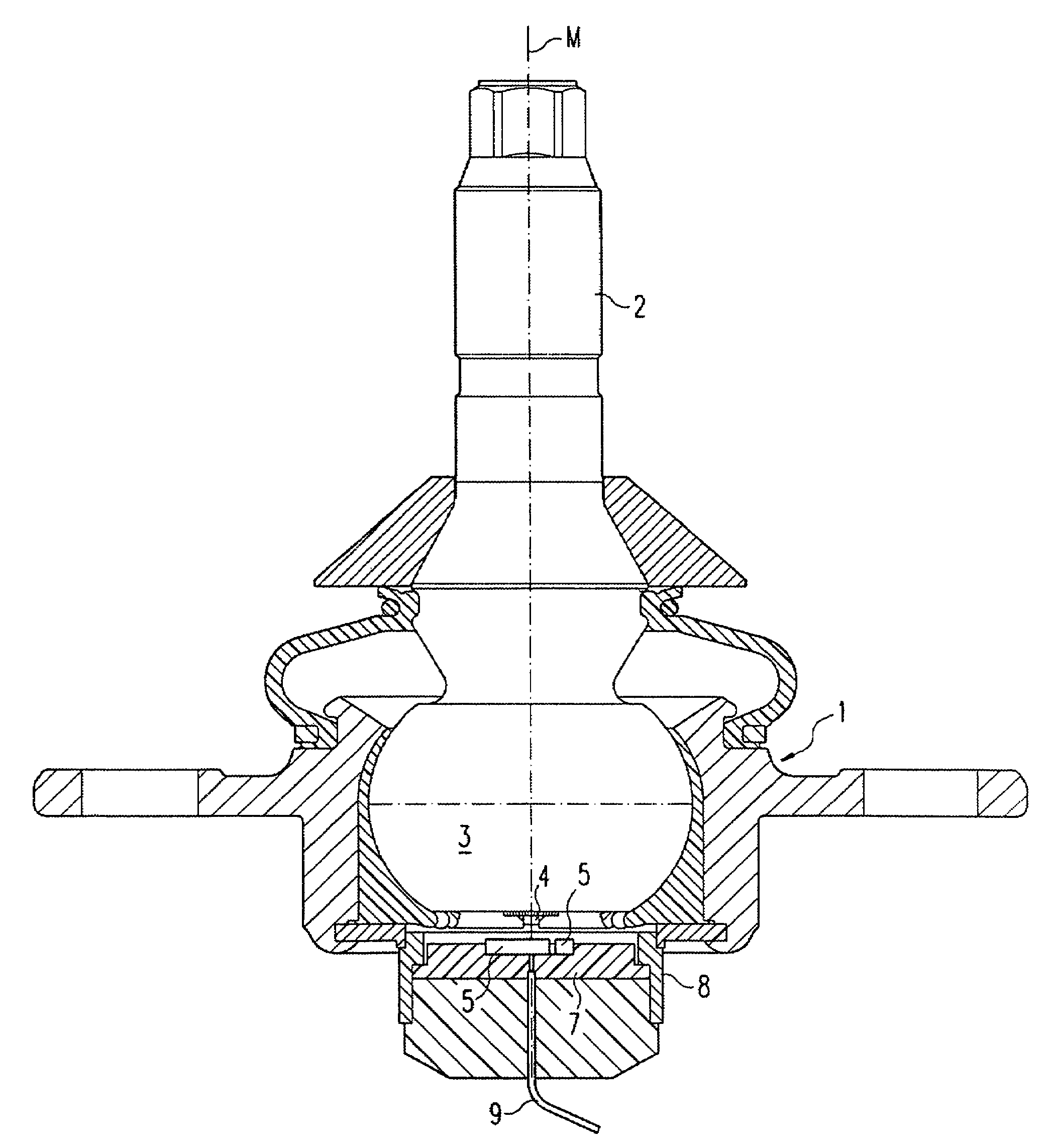
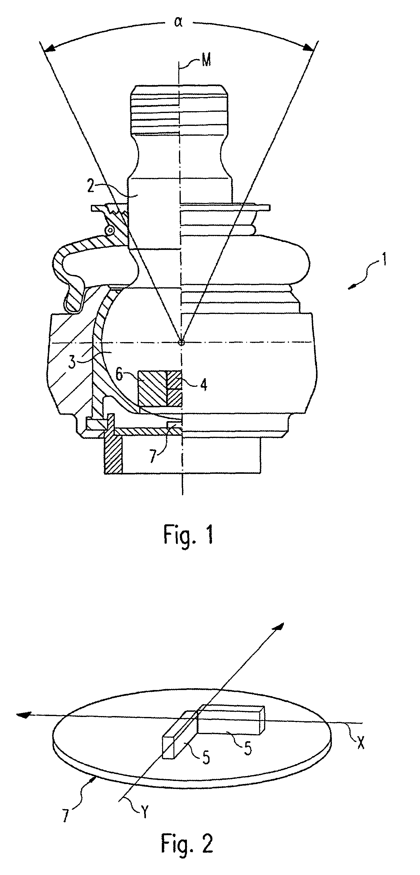
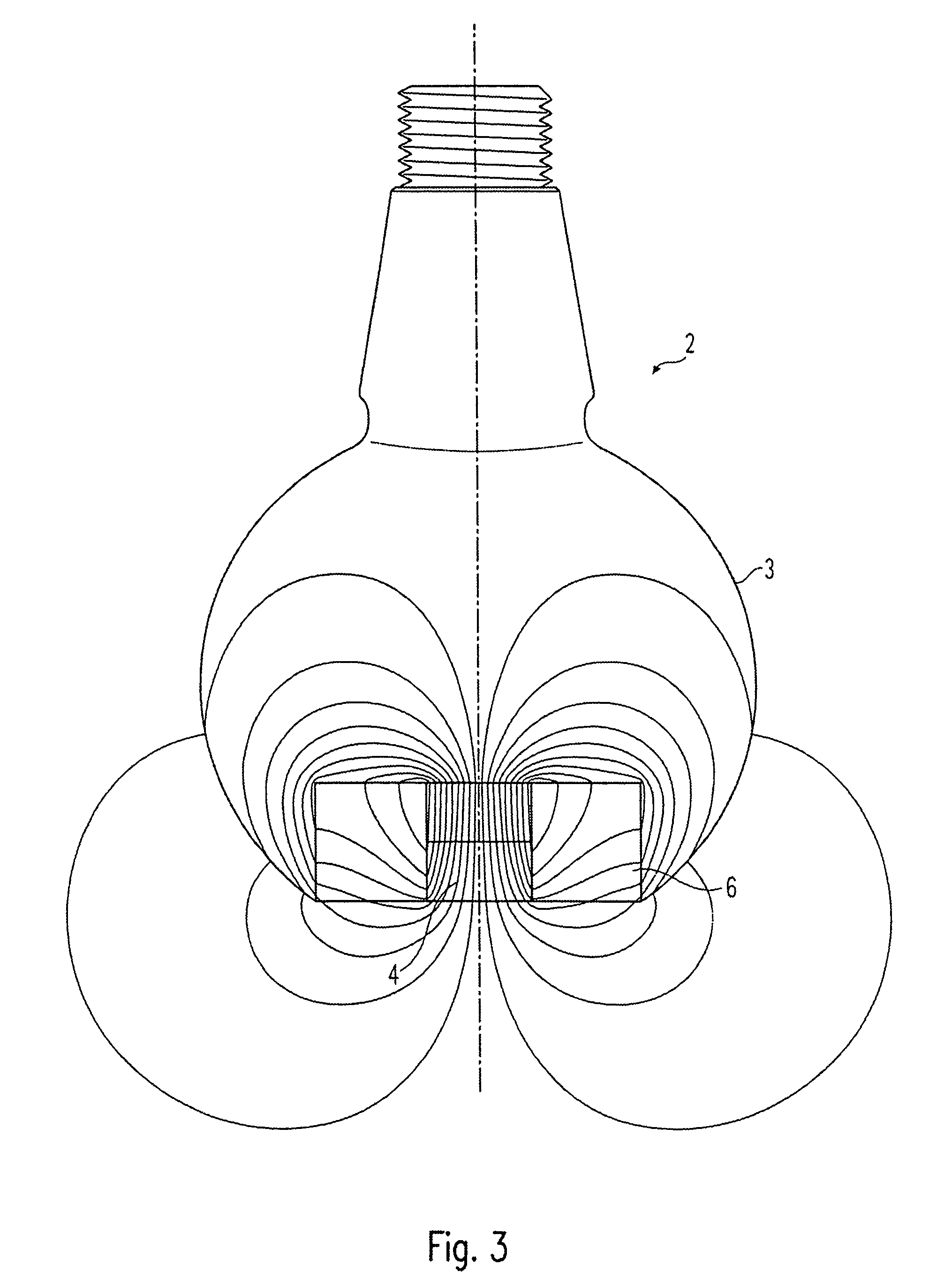
[0019]Referring to the drawings in particular, the ball and socket joint shown in a partial section in FIG. 1 comprises a ball and socket joint housing 1 and a ball pivot 2 mounted with its joint ball 3 in the ball and socket joint housing 1. The ball and socket joint shall be used in the chassis of a vehicle as a vehicle level transducer, whose signals can be used, for example for the static or dynamic headlight and / or vehicle level control, wherein either the ball and socket joint housing 1 or the ball pivot 2 is connected with the wheel suspension and the ball pivot 2 or the ball and socket joint housing 1 is connected with the chassis of the vehicle.

[0020]The ball and socket joint is arranged here between the wheel suspension and the chassis such that when the position of the vehicle body changes in relation to the wheel suspension, the ball pivot 2 is deflected in the ball and socket joint housing 1, and this deflection truly reflects the change in the position of the vehicle b...


PUM


Abstract

A ball and socket joint with integrated angle sensor, especially for use as a vehicle level control in the chassis of a motor vehicle. The ball and socket joint has a ball and socket joint housing (1), a ball pivot (2) mounted in the ball and socket joint housing (1), a bipolar field transducer (4) arranged at the joint ball (3) of the ball pivot (2), and at least one magnetic field direction sensor (5), which is arranged at the ball and socket joint housing (1) and interacts with the magnetic field generated by the field transducer (4), wherein only one pole of the bipolar field transducer (4) is arranged on the surface of the ball.

Description

CROSS REFERENCE TO RELATED APPLICATIONS[0001]This application is a United States National Phase application of International Application PCT / DE2004 / 001855 and claims the benefit of priority under 35 U.S.C. § 119 of German Application DE 103 39 126.6 filed Aug. 22, 2003, the entire contents of which are incorporated herein by reference.FIELD OF THE INVENTION[0002]The present invention pertains to a ball and socket joint with an integrated angle sensor, especially for use as a vehicle level sensor in the chassis of a motor vehicle.BACKGROUND OF THE INVENTION[0003]The use of a ball and socket joint as a vehicle level sensor for the contactless and continuous measurement of the changes in the position of the vehicle body in motor vehicle chassis, wherein the ball and socket joint housing and the ball pivot are arranged between the vehicle chassis and the wheel suspension, is known from EP 617 260 A1. It is proposed in that document that the information obtained from the vehicle level se...

Claims


Application Information

Patent Timeline
Patent Type & Authority Patents(United States)
IPC IPC(8): G01B7/14G01B7/30B60G7/00B60G17/015F16C11/06G01D5/16
CPCB60G7/005B60G17/015F16C11/0642B60G2204/11B60G2204/416B60G2400/00B60G2204/1162F16C41/007F16C11/0604F16C11/0633F16C2326/05F16C2233/00F16C41/00F16C11/06B60G7/00G01D5/12
Inventor SPRATTE, JOACHIMLOREIT, UWE
Owner ZF FRIEDRICHSHAFEN AG
Why Eureka
Try Eureka