
Fixing device and image forming apparatus including a heating roller with multiple heaters

a technology of fixing device and heating roller, which is applied in the direction of electrographic process, manufacturing tools, instruments, etc., can solve the problems of temperature offset, gloss unevenness, and inability to set the light distribution to zero %, so as to prevent the generation of gloss unevenness and prevent the deterioration of the imag

Inactive Publication Date: 2008-07-29
SEIKO EPSON CORP
View PDF10 Cites 11 Cited by
  • Summary
  • Abstract
  • Description
  • Claims
  • Application Information

AI Technical Summary

Benefits of technology

[0011]In order to solve the problems, it is an object of the invention to prevent the generation of the gloss unevenness of an image due to the peak of a heat distribution, the generation of a high temperature offset and the temperature ripple on the heating roller so that a deterioration in the image is prevented.
[0012]It is another object of the invention to prevent an increase in a variation in the control of a fixing temperature due to the ON / OFF operation of a second heater and the generation of a gloss unevenness, thereby preventing a deterioration in picture quality.

Problems solved by technology

However, the holding portion filament emits a light so that a light distribution cannot be set to be zero %.
As a result, if the light distribution peak is present in an image region, there is a problem in that a gloss unevenness is generated on an image or a high temperature offset is generated.
Consequently, there is a problem in that a gloss unevenness is generated on an image in the region in which the non-light emission is to be carried out.
Consequently, precision in the detection of a temperature sensor for controlling the first heater is deteriorated and a variation in the control of a fixing temperature is increased.
Thus, there is a problem in that a gloss unevenness is generated.

Method used


Image

  • Fixing device and image forming apparatus including a heating roller with multiple heaters
  • Fixing device and image forming apparatus including a heating roller with multiple heaters
  • Fixing device and image forming apparatus including a heating roller with multiple heaters

Examples


Embodiment Construction

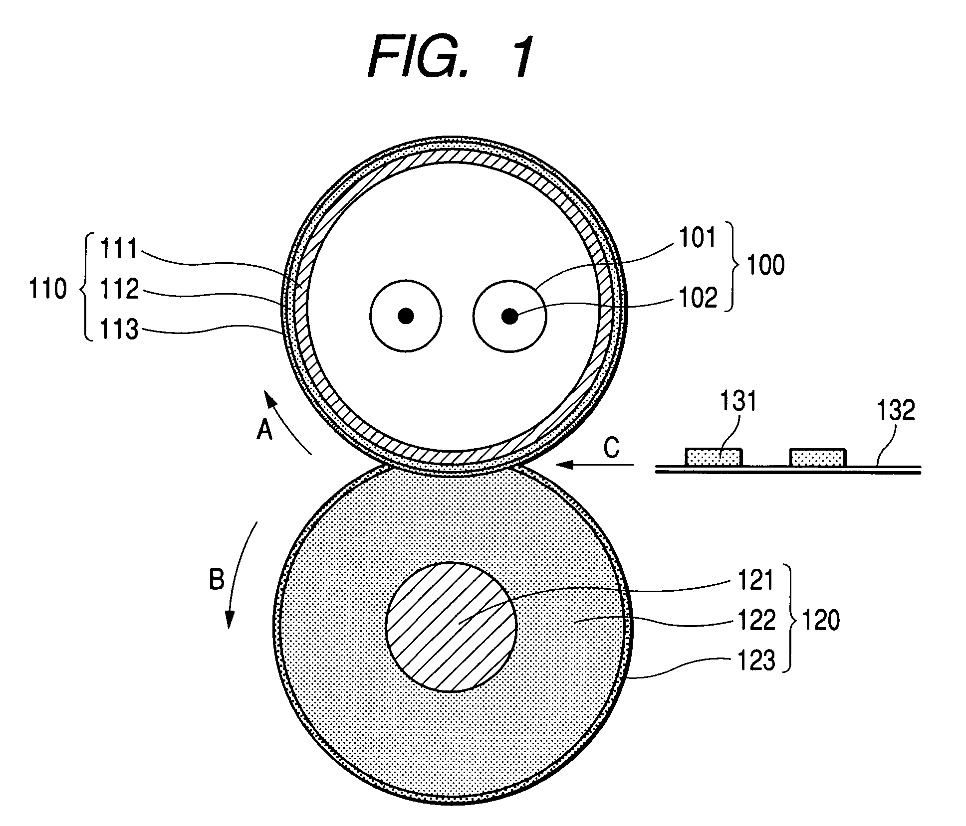
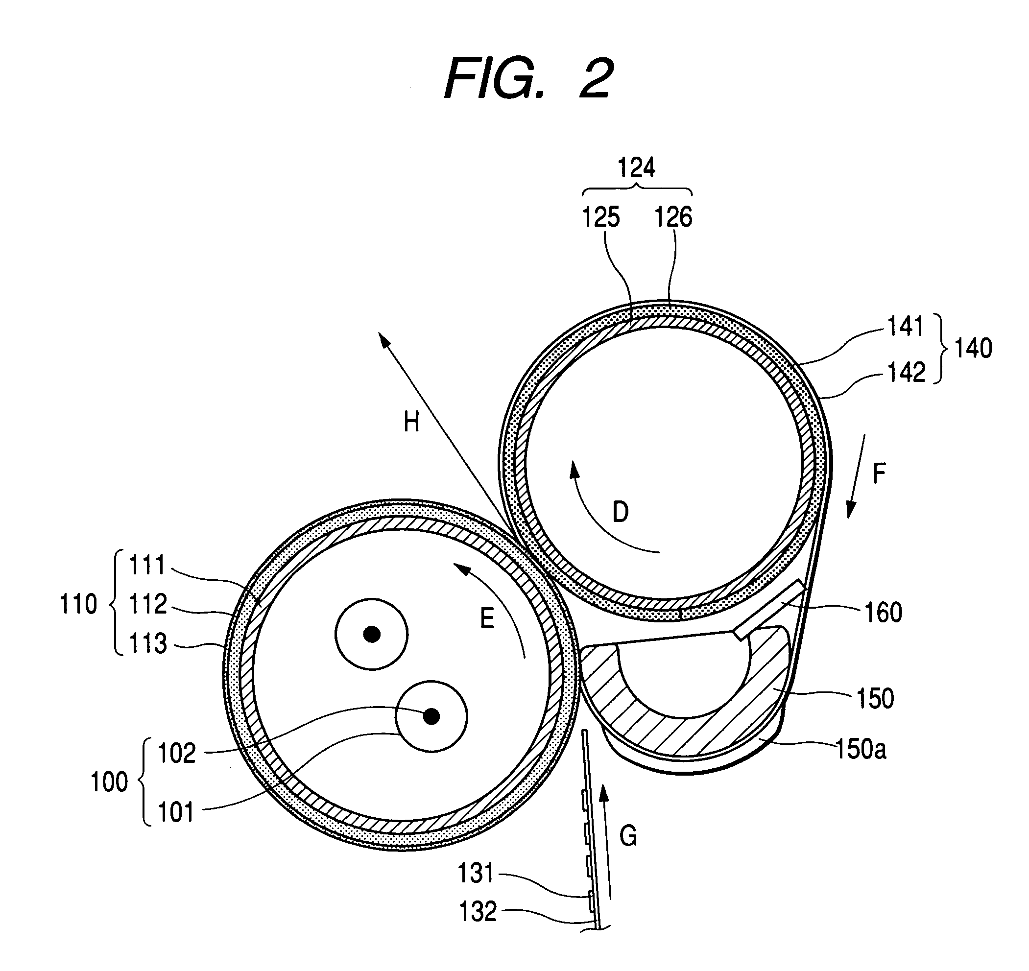
[0061]Embodiments of the invention will be described below with reference to the drawings. FIG. 1 is a view showing an embodiment of a fixing device according to the invention and FIG. 2 is a view showing another embodiment of the fixing device according to the invention.

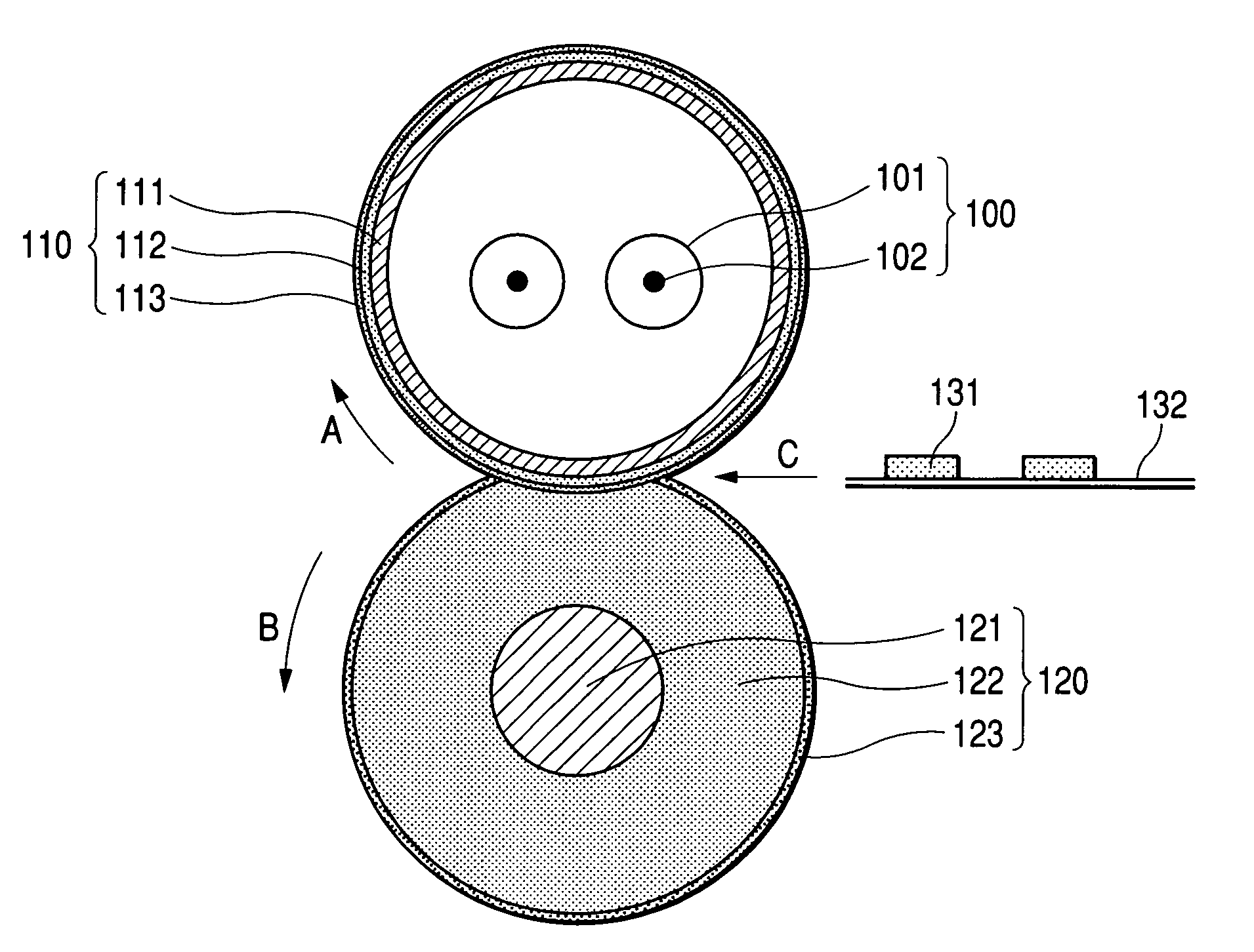
[0062]In the embodiment shown in FIG. 1, a halogen lamp 100 is formed by putting a tungsten filament 102 in a quartz glass tube 101, and a heating roller 110 has a pipe member accommodating two heaters including a central region heating heater (a first heater) using the halogen lamp 100 and a side end region heating heater (a second heater) which is provided as a core 111, and an elastic layer 112 on the outer periphery of the core 111, and furthermore, a fluororesin layer 113 on an outer periphery thereof which are provided as parting layers. A pressurizing roller 120 has, as parting layers, an elastic layer 122 provided on the outer periphery of a metal shaft 121 and a fluororesin layer 123 provided on an outer pe...


PUM

PropertyMeasurementUnit
Temperatureaaaaaaaaaa
Lengthaaaaaaaaaa
Pressureaaaaaaaaaa

Abstract

In a fixing device for causing a pressurizing roller to come in pressure contact with a heating roller including a central region heating heater for heating a central region and a side end region heating heater for heating a side end region on an outside of the central region, thereby fixing an unfixed toner, or an image forming apparatus comprising the fixing device, an outside of an image region of the heating roller is caused to have a peak of heat distribution of the central region heating heater and heat radiated from both side ends of the heating roller is compensated to flatten the temperature distribution of the image region, thereby preventing a deterioration in an image.

Description

[0001]The present application is based on Japanese Patent Applications Nos. 2003-35907, 2003-35908, 2003-67446 and 2003-73185, the entire contents of which are incorporated herein by reference.BACKGROUND OF THE INVENTION[0002]1. Field of the Invention[0003]The present invention relates to a fixing device for causing a pressurizing roller to come in pressure contact with a heating roller including a central region heating heater (first heater) for heating a central region and a side end region heating heater (second heater) for heating a side end region on the outside of the central region, thereby fixing an unfixed developer, and an image forming apparatus comprising the fixing device.[0004]2. Related Art[0005]As a fixing device of an image forming apparatus, in a fixing device including two heaters using two halogen lamps for a heating roller (see Japanese Patent Publication No. JP-A-8-123230, for example), a first heater having a greater calorific value in the central part of the ...

Claims


Application Information

Patent Timeline
IPC IPC(8): G03G15/20H05B3/00
CPCH05B3/0095G03G15/2042G03G2215/2022
Inventor YOSHIOKA, KENJIROKATSUKI, KIYOTERUARUGA, TOMOE
Owner SEIKO EPSON CORP
Learn More