
Systems and methods for automatically generating 3D wireframe CAD models of aircraft

a technology of automatic generation and aircraft, applied in the field of computer modeling, can solve the problems of insufficient data from configuration engineers, laborious work, and large amount of time and money for manually creating such models, and achieve the effect of accurate typing the names

Active Publication Date: 2008-07-29
THE BOEING CO
View PDF5 Cites 9 Cited by
  • Summary
  • Abstract
  • Description
  • Claims
  • Application Information

AI Technical Summary

Benefits of technology

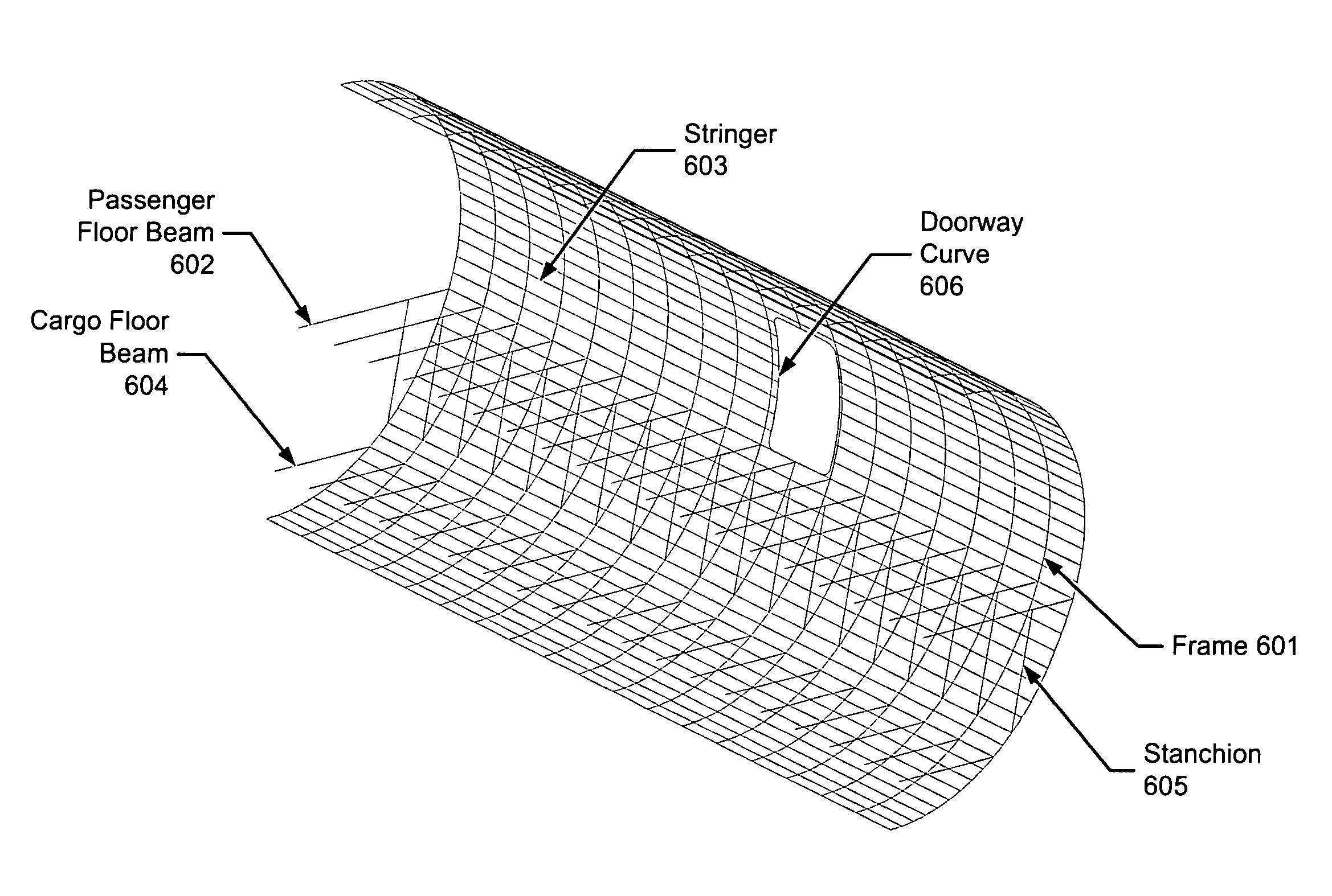
[0012]This invention gives each 3D wireframe element a name attribute according to an agreed upon naming convention. These names are used by downstream applications that used the CAD elements created by this invention. The user is relieved of the tedious burden of interactively propagating the seed points hundreds of times, creating splines through the points and accurately typing the names for all these hundreds of elements.
[0018]As with the fuselage, this invention gives each 3D wireframe element a name attribute according to an agreed upon naming convention. These names are used by downstream applications that use the CAD elements created by this invention. The user is relieved of the tedious burden of interactively laying out the centerlines, projecting them onto the lofts, generating intersection points and ribbon surfaces and accurately typing the names for all these hundreds of elements.

Problems solved by technology

Computer models for analyzing three-dimensional structures may take a great amount of time and money to produce.
Manually creating such a model is slow and often repetitive, tedious work.
Whether this Configuration CAD model is supplied or not, the data from the Configuration engineers is generally insufficient for downstream analysis, such as Finite Element Modeling (FEM) of the airplane, and is typically slowly enhanced by addition of structural elements generated in manual CAD layouts.
The development of the CAD elements, specifically a 3D “wireframe” model, may take many man-hours using existing CAD systems.
Many times, however, the resultant overall CAD model contains inadvertently non-contiguous or redundant CAD elements.
Such elements create problems during computerized analysis such as FEM.
To solve these problems, the analyst must coordinate with the many engineers who contributed to the overall CAD model, resulting in a lot of time-consuming work to repair the model.
Therefore, there exists an unmet need to quickly and easily create 3D wireframe CAD models.

Method used


Image

  • Systems and methods for automatically generating 3D wireframe CAD models of aircraft
  • Systems and methods for automatically generating 3D wireframe CAD models of aircraft
  • Systems and methods for automatically generating 3D wireframe CAD models of aircraft

Examples


Embodiment Construction

[0025]The present invention relates to computer-based systems, methods, and computer-program products for automatically creating 3D wireframe CAD models. Many specific details of certain embodiments of the invention are set forth in the following description and in FIGS. 1-10 to provide a thorough understanding of such embodiments. One skilled in the art, however, will understand that the present invention may have additional embodiments, or that the present invention may be practiced without several of the details described in the following description.

[0026]An embodiment of the present invention is a process suitably implemented in software for automatically generating 3D wireframe CAD models on a stand-alone computer, or a computer coupled to other computers or computer systems over a network.

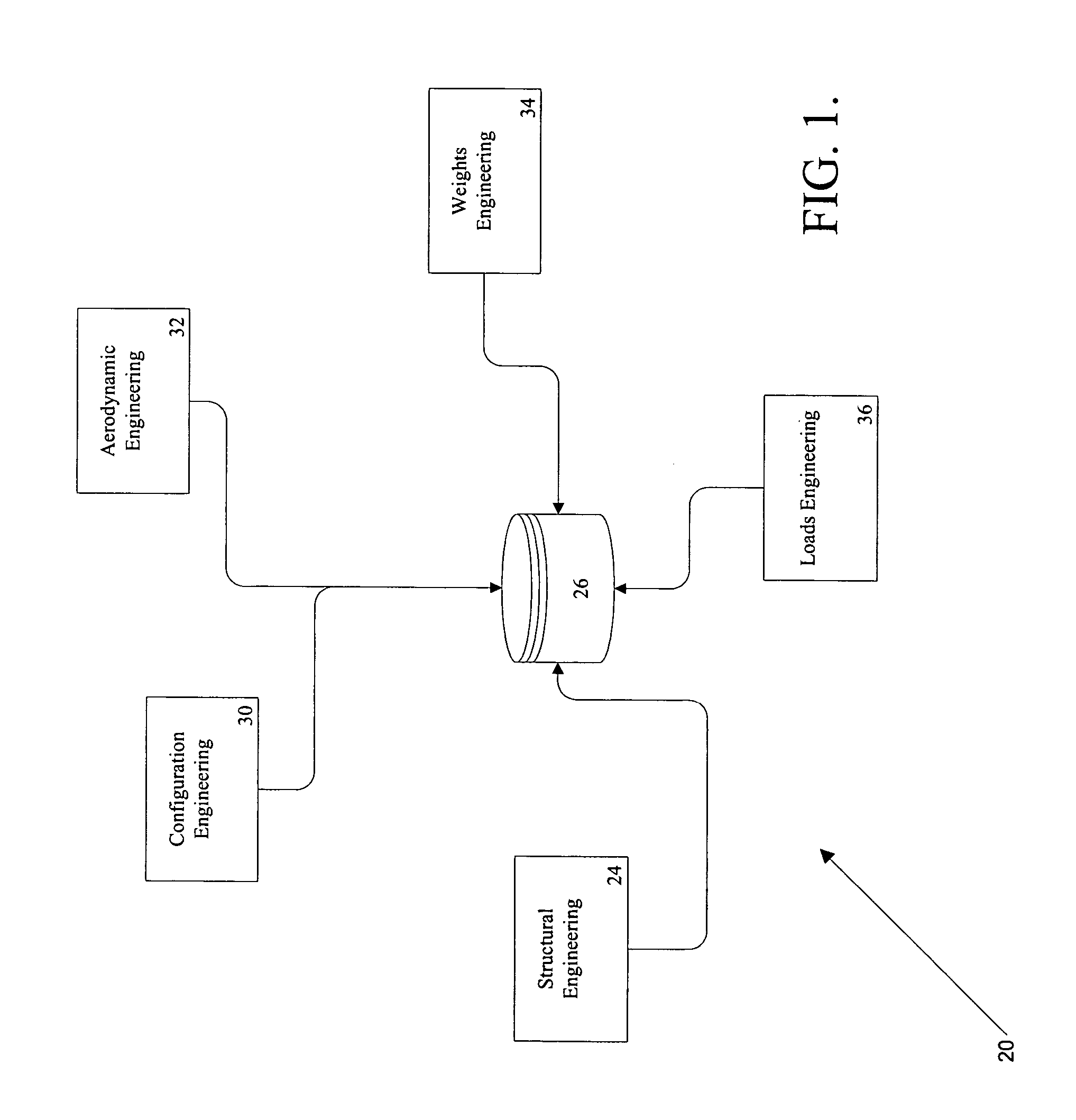
[0027]Referring to FIG. 1, an embodiment of the present invention is implemented in a network-based system 20 that includes a structures group 24 coupled to a database 26, a Configurations g...


PUM


Abstract

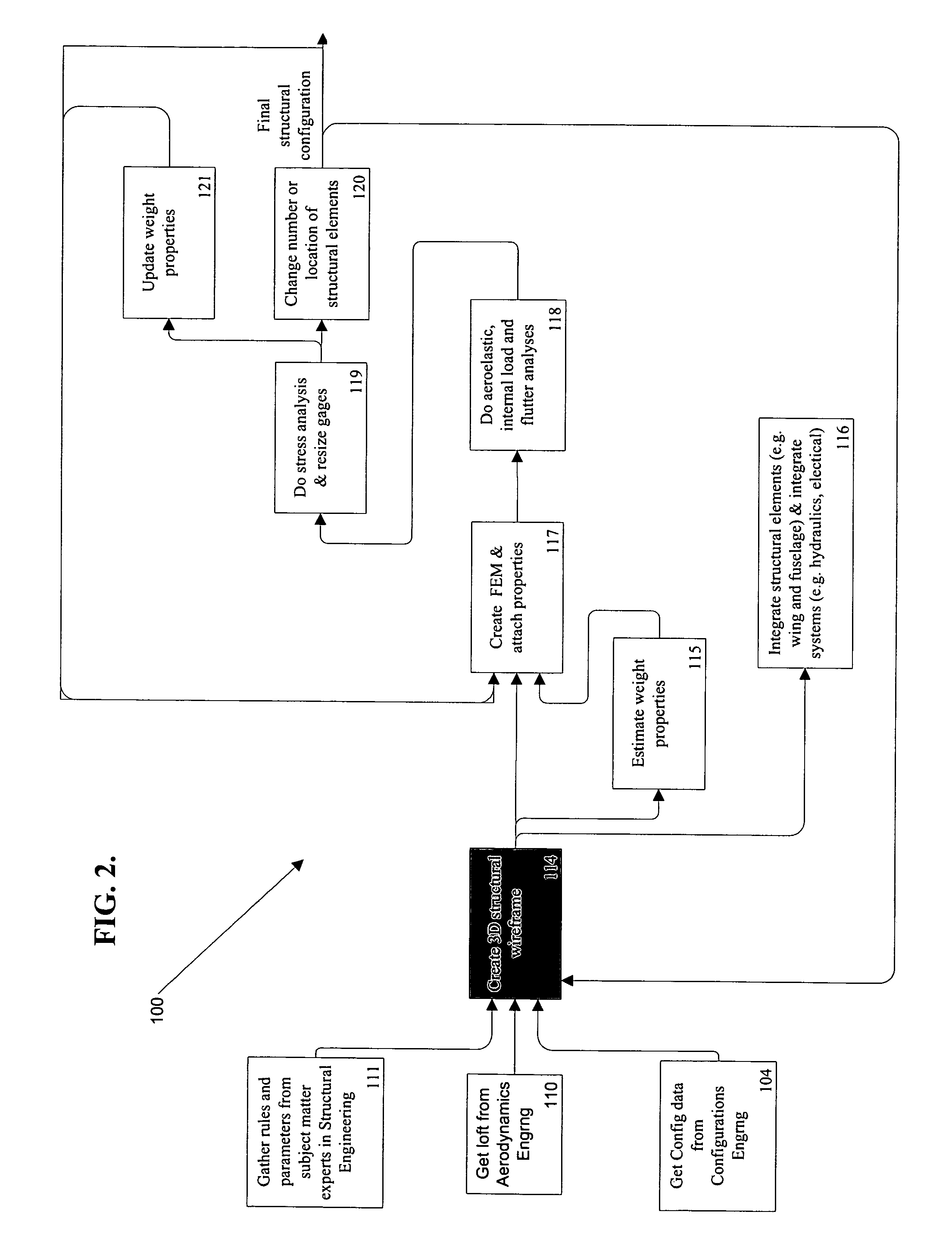
Computer-based systems, methods, and computer-program products for automatically creating three dimensional geometric models are provided. The geometric models may be used to generate finite element models for computer modeling and loads testing. Automatically creating geometric models includes generating a surface curve based on surface and parameter information at all frame locations. Stringer points are automatically spaced on the first generated surface curve based on the parameter information. The stringer seed points are then propagated to the other frame curves based on parameter information. A stringer curve is automatically generated for each set of corresponding stringer points. The generated stringer curves are automatically projected onto the surface. All points, projected curves, lines and ribbon surfaces are named according to a naming convention established by the user to facilitate the automatic importation of the CAD elements into a FEM preprocessor program.

Description

FIELD OF THE INVENTION[0001]This invention relates generally to computer modeling and, more specifically, to automated computer modeling.BACKGROUND OF THE INVENTION[0002]Computer models for analyzing three-dimensional structures may take a great amount of time and money to produce. For example, a Computer Aided Design (CAD) representation of an airplane typically includes simple lines and curves representing the centerline of each primary structural element of the airplane. Manually creating such a model is slow and often repetitive, tedious work.[0003]When a new airplane or airplane derivative concept is proposed, by engineers in the Configuration engineers, it is presented to the other engineering disciplines (e.g. Structures, Aerodynamics, Loads, Weights) as a Configuration Memo. At the same time the Configuration engineers may release a very simplified CAD model based on the Configuration Memo. This Configuration CAD model consists of two dimensional elements, with the fuselage ...

Claims


Application Information

Patent Timeline
Patent Type & Authority Patents(United States)
IPC IPC(8): G06F17/50G06F19/00B64C1/00G06T17/00G06T17/20
CPCG06T17/20G06F17/5095G06F30/15
Inventor FOX, MICHAEL K.GALUSKA, MICHAEL D.SEONG, BRIAN H.
Owner THE BOEING CO
Learn More