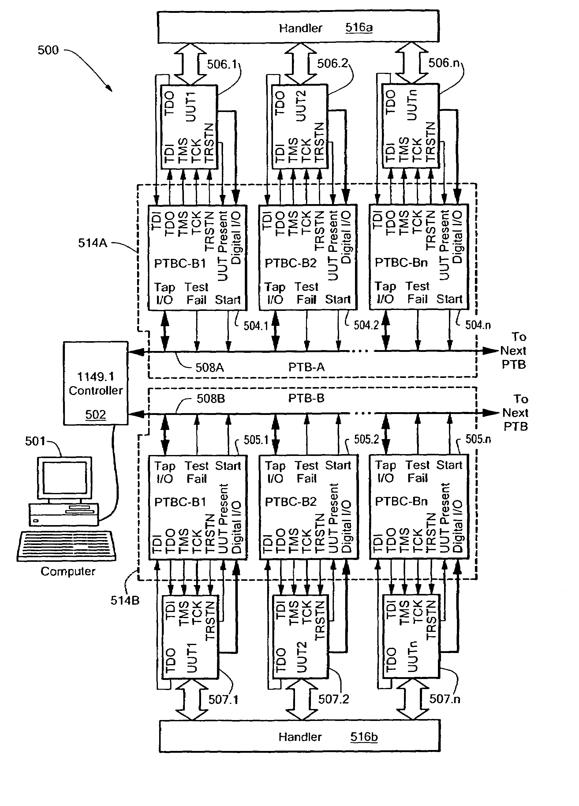
In recent years, there has been a significant increase in the cost of testing and configuring electronic circuits and systems.
One factor contributing to the higher test and configuration costs is the increased use of programmable memories such as FLASH, and programmable logic devices such as Complex Programmable Logic Devices (CPLDs) and Field Programmable Gate Arrays (FPGAs).
Another contributing factor is the increased size and complexity of these programmable devices.
As a result, the time required to program such configuration data has increased, thereby increasing manufacturing and end-product costs, which are typically passed along to the customer.
Still another factor contributing to higher product costs is the continuing increase in manufacturing test times. Electronic products are normally tested following fabrication and
assembly to assure that no defects have been introduced into the manufacturing process.
As such electronic products have continued to offer more features, higher performance, and
reduced size, the ICs and PCBs used to make these products have become more complex and more highly integrated.
This has resulted in increased amounts of
test data and increased manufacturing test times, which have further increased manufacturing and end-product costs.
In this way, multiple UUTs can be tested and configured in the same amount of time as a single unit, thereby reducing the effective per-unit test / configuration times. Such techniques can improve throughput, especially when the index times are significantly shorter than the per-unit test and configuration times. However, merely increasing the number of UUTs that are tested and configured in parallel is not always enough to achieve a desired level of throughput, even when
massively parallel testing techniques are employed.
Further, parallel testing alone does not always result in the maximum achievable level of throughput.
Moreover, conventional parallel testing techniques are often prohibitive in terms of cost.
Although conventional testers can be used for ganged and multi-site test and configuration, such testers are typically limited in the number of units that can be tested and configured in parallel.
Such limitations are inherent in the tester's architecture, which depends on individual tester channels and the pattern memory associated with these channels to provide the parallelism required for multi-
site testing.
Because the channels and memory are limited in number and capacity in these tester architectures, there is a limit to the number of units that can be tested or configured simultaneously.
As such, conventional tester architectures are not readily scalable for parallel testing, and so their costs often rise prohibitively as the requirements for parallelism and tester resources increase.
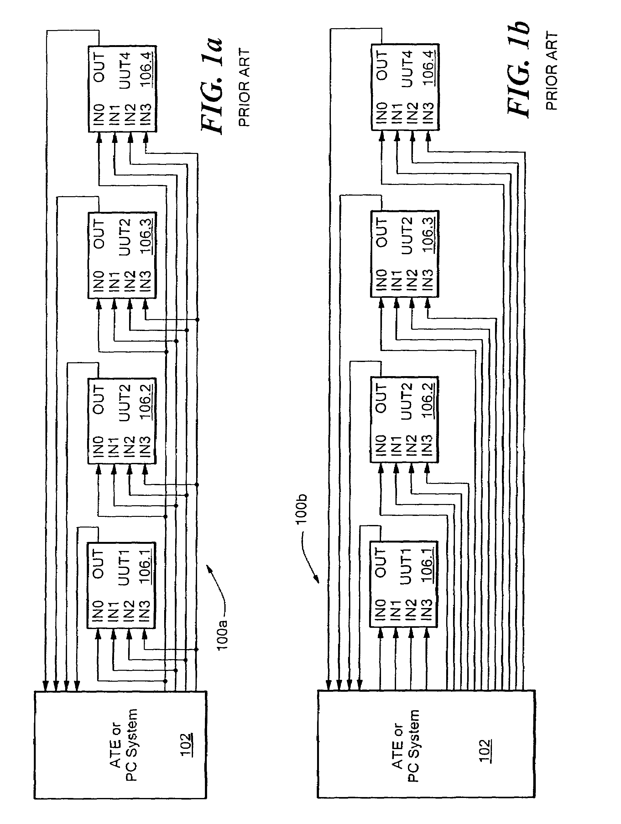
However, there is a drawback in that an individual UUT cannot receive
test data separate from the other UUTs 106.1-106.4.
However, because PCBs and ICs may have hundreds or even thousands of inputs and outputs, the number of inputs / outputs may rapidly exceed the number of tester channels available, even for relatively small numbers of UUTs.
As such, the ganged test and multi-site test configurations 100a-100b of FIGS. 1a-1b are not readily expandable, and so it is typical that only a relatively small, limited number of UUTs can be tested and configured in parallel with these tester configurations.
However, this can be a costly approach to expanding the tester, and there is still a limit to the number of parallel sites that can be configured for a particular type of UUT.
Although there are alternative ways that ganged and multi-
site testing can be configured and performed, these alternative approaches also have limitations in the number of UUTs that can be tested and configured simultaneously.
Such limitations are typically inherent in the ATE architectures and the approaches used.
Further, the number of UUTs that can be tested simultaneously using conventional ATE is often relatively small in number.
Consequently, with these conventional approaches, the number of UUTs that can be handled, tested, and configured in parallel is generally dictated by the limitations of the ATE or PC system, and not the requirements for test and configuration throughput.
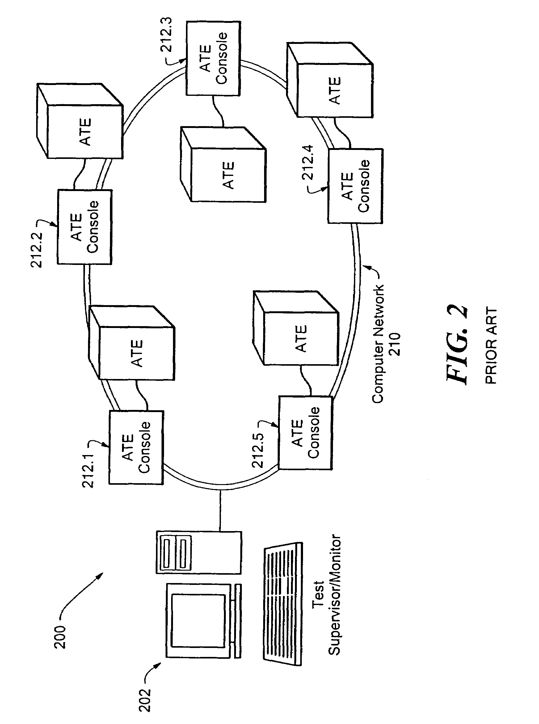
However, expansion using the approach of FIG. 2 can be costly because it typically requires the addition of one or more ATEs and ATE consoles.
However, this approach does not use parallel testing, and typically does not provide for an optimal level of throughput.
Dual well testing only affects the overall throughput by reducing the handling time for removing a tested PCB and inserting another PCB.
Such an arrangement may contribute to
signal integrity problems in the test environment, especially when testing high-speed signals on the PCBs.
Accordingly, the conventional techniques described above for providing test and / or configuration of ICs, PCBs, and electronic sub-assemblies and systems are generally incapable of providing an optimal or maximum achievable level of throughput.
Although this is due at least in part to the limitations of the ATE or PC system, it is primarily due to the misconception that simply increasing the number of UUTs tested and configured in parallel will result in an increased throughput.
With a single tester resource, there is little flexibility in adjusting the handling or determining the number of UUTs that can be tested and configured in parallel.
This is because the throughputs are typically dictated by cost and resource limitations of the ATE, e.g., the number of available tester channels compared to the number of pins per die required for configuration and test.


