

One piece cast steel monobloc piston
a monobloc piston, cast steel technology, applied in the direction of trunk pistons, engine cooling devices, plungers, etc., can solve the problem of restricting the choice of materials to aluminum or cast iron
- Summary
- Abstract
- Description
- Claims
- Application Information
AI Technical Summary
Benefits of technology
Problems solved by technology
Method used
Image

Examples
Embodiment Construction
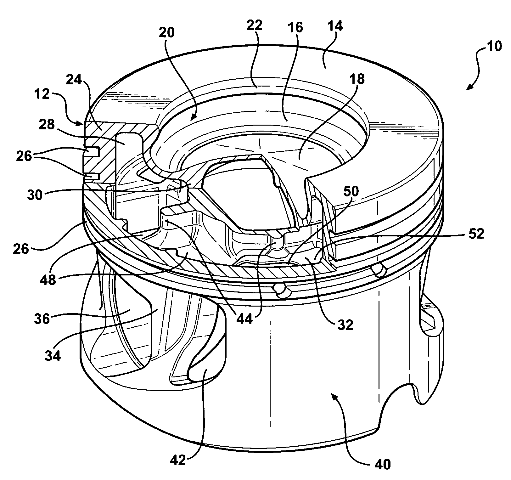
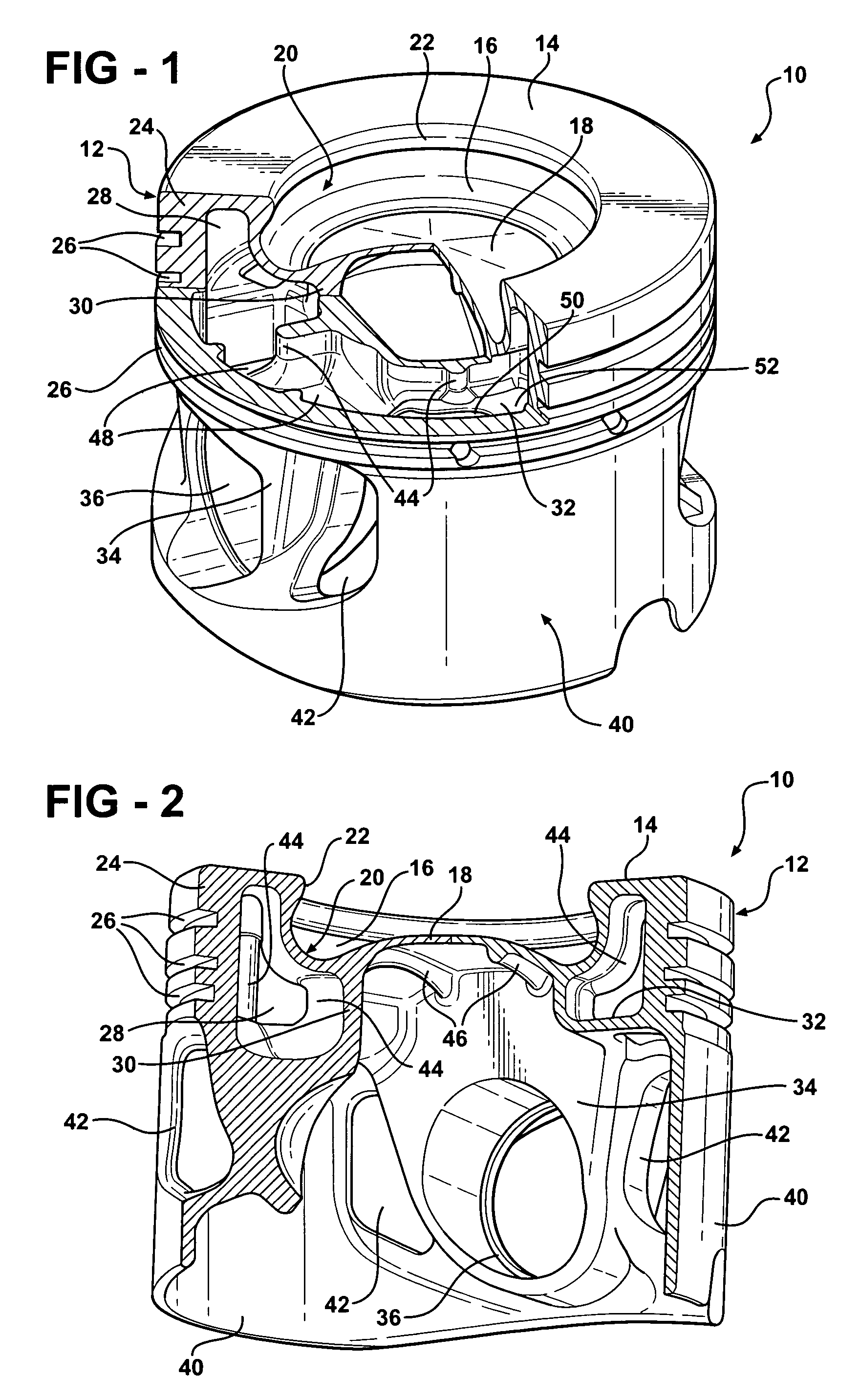
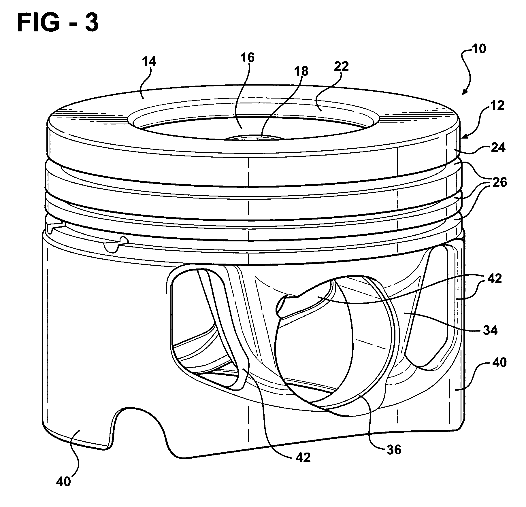
[0013]A piston constructed according to an embodiment of the invention is shown generally at 10 in the drawings. The piston is of a monobloc construction and cast entirely of one piece of steel, and preferably of SAE 4140H steel. The piston has an upper head portion 12 formed with an upper wall 14 that is generally planar and includes a combustion bowl 16 recessed into the upper wall 14 and bounded by a contoured combustion bowl wall 18 that includes an undercut corner region 20 that extends radially outwardly of an upper lip 22 of the combustion bowl 16 to provide a reentrant structure to the combustion bowl 16. Inward of the undercut region 20, the combustion bowl wall 18 is dome-shaped, with the center of the dome-shaped wall 18 rising above the under cut region 20 toward the upper wall 14, but terminating below the lip 22.
[0014]The head portion 12 further includes an outer annular ring belt wall 24 that extends downwardly from the upper wall 14 and is formed with a plurality of ...
PUM
 Abstract
Description
Claims
Application Information