Nozzleless conveyor belt and sprocket cleaning shaft

a conveyor belt and nozzleless technology, applied in the direction of cleaning process and equipment, cleaning using liquids, chemistry apparatus and processes, etc., can solve the problems of affecting the operation of equipmen

Inactive Publication Date: 2008-08-05
FARRIS MIKE +1
View PDF14 Cites 29 Cited by
  • Summary
  • Abstract
  • Description
  • Claims
  • Application Information

AI Technical Summary

Benefits of technology

[0017]It is therefore an object of the present invention to provide a nozzleless belt-cleaning sprocket support shaft for cleaning endless conveyor belts and the sprockets supported thereon that eliminates the need for nozzles that project from the surface of the shaft and their inherent exposed screw threads and exposed projecting surface areas, which tend to accumulate liquids and debris and promote growth of bacteria, biofilms, and cross-contamination.
[0018]It is another object of this invention to provide a nozzleless belt-cleaning sprocket support shaft for cleaning endless conveyor belts and the sprockets supported thereon that discharges cleaning fluid under pressure through a plurality of elongate narrow longitudinally spaced offset slits in a wide fan spray pattern onto the inside surface of the conveyor belt and through crevasses, joints, hinges, interfaces and openings in the belt to effect efficient cleaning of the belt.
[0019]It is another object of the present invention to provide a nozzleless belt-cleaning sprocket support shaft for cleaning endless conveyor belts and the sprockets supported thereon that discharges cleaning fluid under pressure between the exterior surfaces of the shaft and interior surfaces of the bore of the sprockets supported thereon to efficiently clean the overlapping surfaces, which would otherwise tend to accumulate liquids and debris and promote growth of bacteria, biofilms, and cross-contamination.

Problems solved by technology

The items being transported may leak or ooze liquids of varying viscosity, or shed dust, dirt, particles or debris that can accumulate on the belt and foul the conveyor.
Such organic matter, if allowed to accumulate on the belt and / or other components, presents a health hazard because it quickly decays, and can cause growth of bacteria, biofilms, and cross-contamination.
The cleaning requirements cause a necessary, but time-consuming, downtime of the equipment and delay in production, and additional time and effort must be expended to re-assemble the conveyor.
One of the major problems with these types of conveyor systems is that, organic matter and the various liquids and debris tend to work their way into and through crevasses, joints, hinges, interfaces and openings in the belt and a substantial amount of unwanted organic matter thereby accumulates on the inside surface of the belt and on the drive components such as the drive sprockets, idler sprockets and support rollers.
Generally, the inside surface of the belt and the drive components are not easily accessible for cleaning, requiring that the conveyor be regularly shut down and disassembled to effect a thorough cleaning.
Another problem with these types of conveyor systems is that the structural components and the drive and idler sprocket assemblies are constructed and / or assembled in a manner that produces ledges, pockets, exposed screw threads, exposed nuts or fasteners, surfaces that overlap and form laminations, all of which also tend to accumulate liquids and debris from the food being transported and present a health hazard due to growth of bacteria, biofilms, and cross-contamination.
One of the disadvantages of the single elongated sprocket cleaning system of U.S. Pat. No. 6,367,613 and Published Application 2002 / 0117381 is that the plurality of nozzles project from the valley surface of the sprocket between radially spaced longitudinal teeth, thus, the nozzles and sprocket assembly provides exposed projecting surface areas that could accumulate liquids and debris and promote growth of bacteria, biofilms, and cross-contamination.
The placement of the nozzles also limits the coverage area for fluids being emitted from the nozzles onto the conveyor belt.
One of the disadvantages of the pie-shaped sector sprocket assembly of U.S. Pat. No. 6,740,172 is that the nozzles and set screws or snap rings provide exposed screw threads and projecting surface areas, and the laterally mounted pie-shaped sectors and hubs provide overlapping surfaces, which could accumulate liquids and debris and promote growth of bacteria, biofilms, and cross-contamination.
The nozzle and sprocket arrangement also requires time and labor to remove and reinstall a plurality of nozzles each time a sprocket is replaced, or when the sprocket assembly is dismantled for cleaning.
The nozzles are also fixed to the non-rotating shaft and do not rotate along with the conveyor belt, which limits the coverage area for fluids being emitted from the nozzles onto the conveyor belt.
One of the disadvantages of the conveyor belt cleaning sprocket assembly of U.S. Pat. No. 6,978,880 is that the outwardly extending nozzles provide exposed screw threads and projecting surface areas, and the square bar and bore of the mounting arrangement of the sprockets provides overlapping flat surfaces, which could accumulate liquids and debris and promote growth of bacteria, biofilms, and cross-contamination.
The nozzle and sprocket arrangement also requires time and labor to remove and reinstall a plurality of nozzles each time a sprocket is replaced, or when the sprocket assembly is dismantled for cleaning.

Method used


Image

  • Nozzleless conveyor belt and sprocket cleaning shaft
  • Nozzleless conveyor belt and sprocket cleaning shaft
  • Nozzleless conveyor belt and sprocket cleaning shaft

Examples


Embodiment Construction

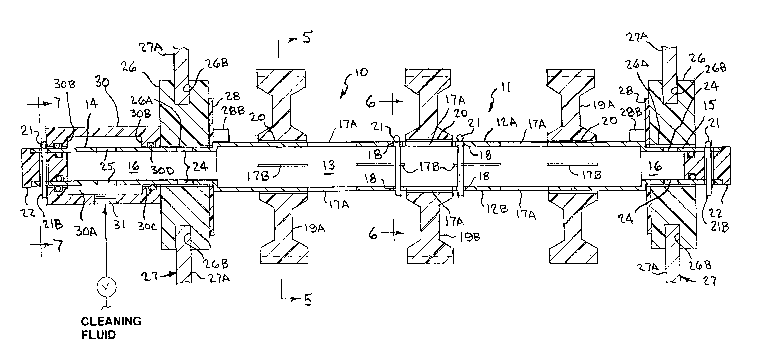
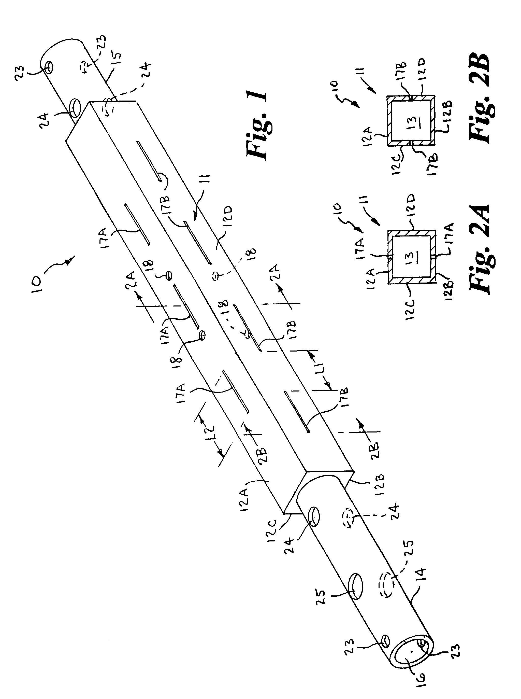
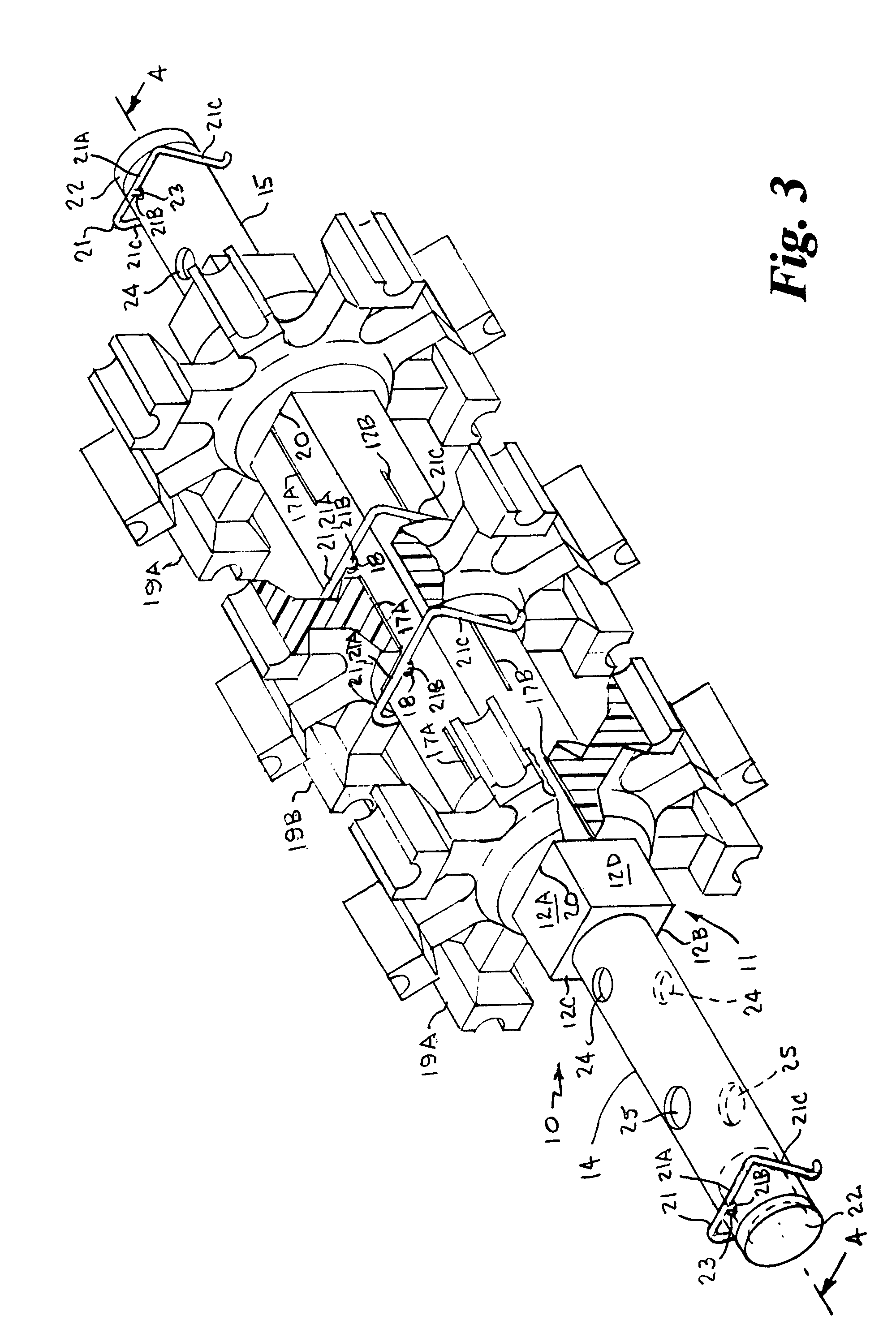
[0037]Referring to the drawings by numerals of reference, there is shown in FIGS. 1, 2A and 2B, a preferred nozzleless belt-cleaning sprocket support shaft 10 for cleaning endless conveyor belts and the sprockets supported thereon. The sprocket support shaft 10 has an elongate hollow midsection or central portion 11 of square transverse cross section with parallel spaced opposed side walls 12A, 12B, 12C and 12D, defining a central interior chamber 13, and cylindrical opposed ends 14 and 15 extending axially outward therefrom. One cylindrical end 14 is longer than the other end 15. A central bore 16 extends axially through the opposed cylindrical ends 14, 15 in communication with the interior chamber 13 of the hollow central portion 11.

[0038]A plurality of elongate narrow slits 17A and 27B are formed in the side walls 12A, 12B, 12C and 12D in longitudinally spaced apart relation along the length of the square midsection or central portion 11. The slits 17A of two opposed side walls 1...


PUM


Abstract

A nozzleless belt-cleaning sprocket support shaft for cleaning endless conveyor belts has a first end, a second end, a central portion of generally square transverse cross section with a plurality of elongate narrow slits in each of the side walls in longitudinally spaced apart relation along its length, and a plurality of sprockets mounted thereon. Cleaning fluid is simultaneously discharged through the slits in a fan spray pattern onto the inside surface of the conveyor, through crevasses, joints, hinges, interfaces and openings in the belt to effect cleaning of the belt, and between the exterior surfaces of the shaft and interior surfaces of the bores of the sprockets and the bearings that support the shaft to effect cleaning of the overlapping surfaces, during rotation of the belt. The cleaning shaft may be used with various types of conveyor belts and the ends may be mounted in conventional bearings.

Description

BACKGROUND OF THE INVENTION[0001]1. Field of the Invention[0002]This invention relates generally to endless conveyor belt cleaning systems, and more particularly to a nozzleless conveyor belt sprocket support shaft that discharges a cleaning fluid through a plurality of narrow slits to clean the belt, sprockets, and bearings while the conveyor is operating.[0003]2. Background Art[0004]Conveyors comprising sprocket-driven endless belts are typically used for the transport of many articles including produce and food products. The items being transported may leak or ooze liquids of varying viscosity, or shed dust, dirt, particles or debris that can accumulate on the belt and foul the conveyor. In food processing plants, where cuts of meat, poultry, fish and other consumable food products are transported on conveyors, sanitation is a primary concern, because these types of food products ooze blood, deposit viscous or congealed fat, cartilage, muscle, and other animal carcass liquids and...

Claims


Application Information

Patent Timeline
Patent Type & Authority Patents(United States)
IPC IPC(8): B65G45/00
CPCB65G45/22
Inventor FARRIS, MIKEMANCHESTER, DOUGLAS I.
Owner FARRIS MIKE
Why Eureka
Try Eureka