
Adapter for connecting a low voltage light bulb to a standard electrical light socket

a low voltage light bulb and adapter technology, which is applied in the direction of electrical discharge lamps, coupling device connections, lighting and heating apparatus, etc., can solve the problems of inefficient energy consumption, inconvenient installation, and inability to meet the needs etc., and achieve the effect of reducing the overall cost of lighting a room and reducing the cost of consumption

Inactive Publication Date: 2008-08-05
HARLAN WHIL
View PDF5 Cites 14 Cited by
  • Summary
  • Abstract
  • Description
  • Claims
  • Application Information

AI Technical Summary

Benefits of technology

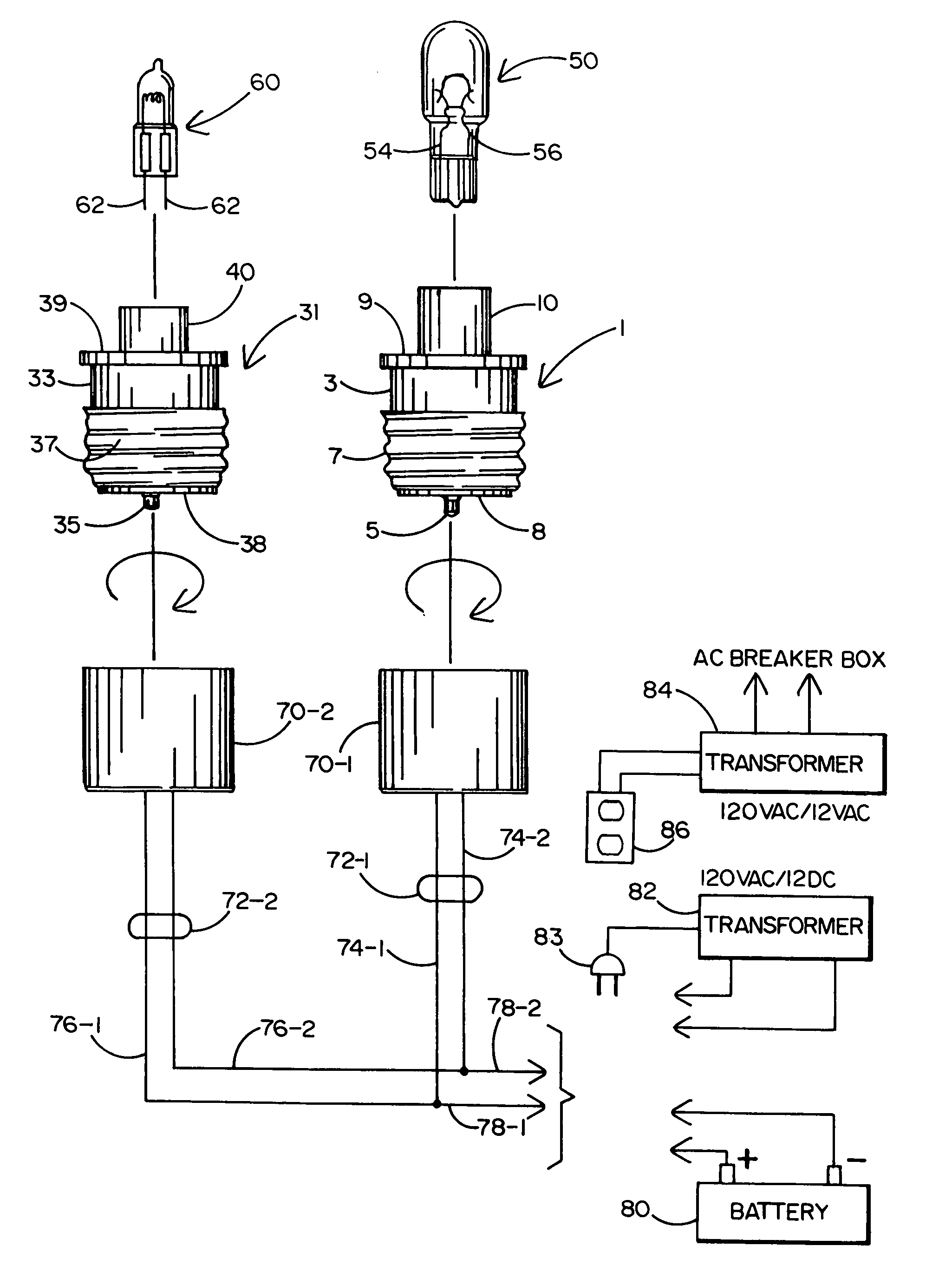
[0006]In general terms, a lamp socket adapter is disclosed that is capable of being rotated into mating engagement with a standard Edison-type lamp socket to be connected to an electrical wall receptacle. By virtue of the lamp socket adapter of this invention, a commercially-available, compact and energy-efficient low voltage light bulb (e.g., such as a wedge-base bulb or a bipin bulb) can be coupled to the Edison lamp socket at which to receive a supply of 12 volts AC or DC, but without having to alter the lamp socket or add a 120 volt to 12 volt converter thereto.
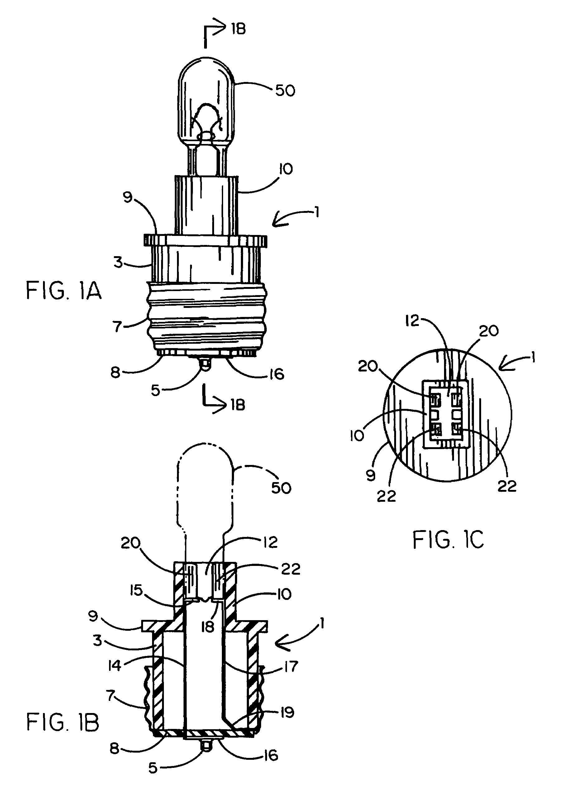
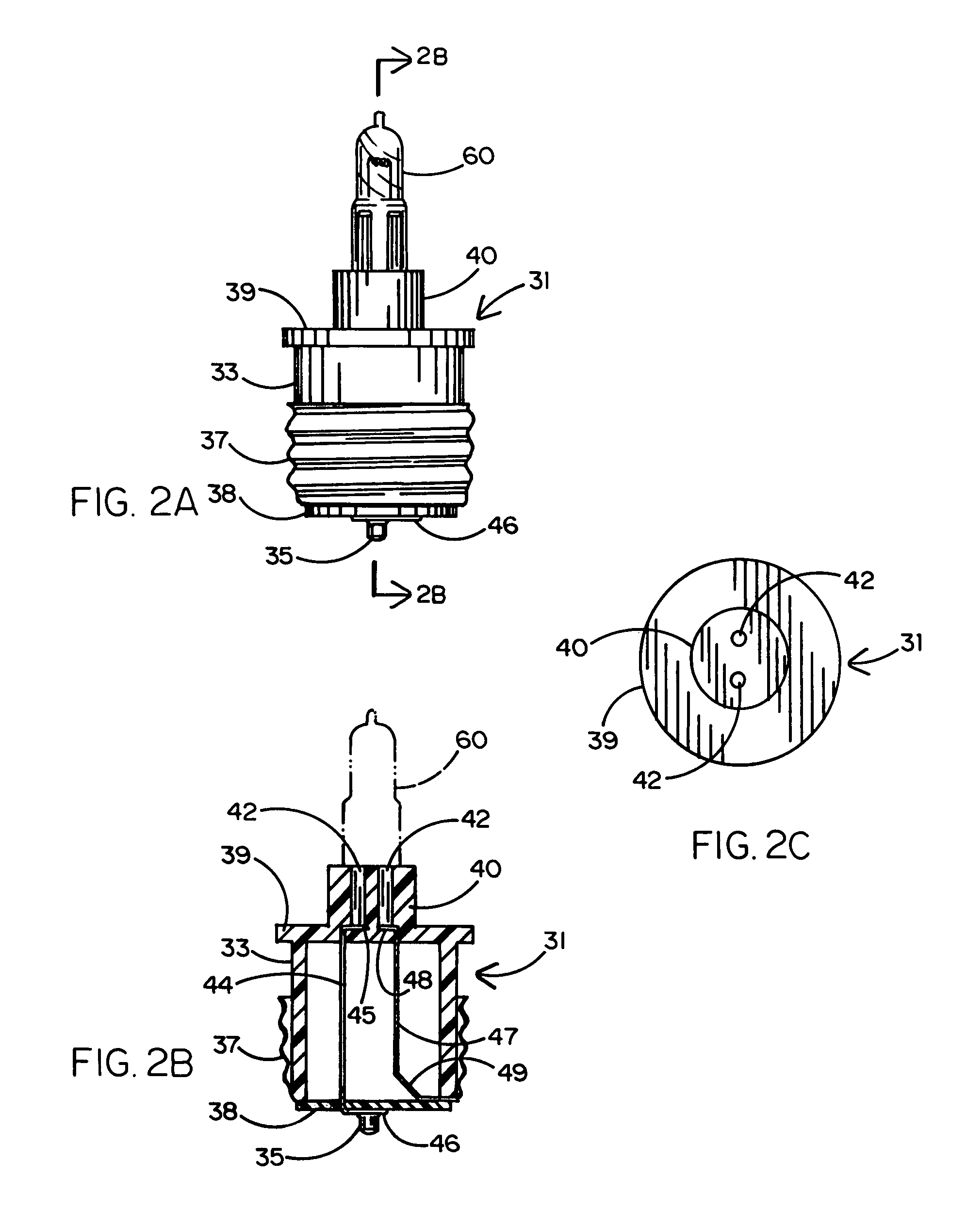
[0007]The lamp socket adapter includes a cylindrical base that is sized for removable receipt by the Edison lamp socket. A conductive center pole located at the bottom of the base and a conductive screw thread surrounding the base are moved into contact with corresponding electrical contacts of the lamp socket. A bulb pedestal stands upwardly from the base to establish a support to which the low voltage bulb is attached. In a first preferred embodiment, where a wedge-base bulb is to be coupled to the adapter, the bulb pedestal has a hollow receptacle within which the bulb is received and retained. Pairs of contacts run through the bulb pedestal by which terminals of the wedge-base bulb are electrically connected to the lamp socket adapter. In a second preferred embodiment, where a bipin bulb is to be coupled to the adapter, the bulb pedestal has a pair of pin holes extending vertically therethrough to receive respective ones of a pair of conductive pins from the bulb. The pins extending through the pair of pin holes are electrically connected to the lamp socket adapter. A first electrically-conductive strip runs through the base of the lamp socket adapter from the center pole thereof to the bulb pedestal at which to be connected to a first terminal / pin of the low voltage light bulb. A second electrically-conductive strip runs through the base of the lamp socket adapter from the screw thread thereof to the bulb pedestal at which to be connected to a second terminal / pin of the low voltage light bulb.
[0008]A plurality of low voltage (e.g., wedge base and / or bipin) light bulbs can be interconnected to one another in a lighting circuit to receive a 12 volt AC or DC supply at the lamp sockets to which respective lamp socket adapters have been mated. A suitable AC or DC voltage can be supplied to the lamp sockets, for example, from a battery, a transformer that is electrically connected to an AC wall receptacle, or a transformer that is connected via a dedicated circuit to the AC breaker box of a house or other residential facility to be lighted.

Problems solved by technology

However, it is well known that using the conventional AC-powered light bulb results in an inefficient consumption of energy.
In this same regard, the standard 120 volt AC-powered incandescent light bulb has a relatively short life expectancy.
Therefore, the overall cost to the consumer to light a room is undesirably high.
What is more, because of its relatively large size, the AC-powered incandescent light bulb is not well suited for recessed lighting applications.

Method used


Image

  • Adapter for connecting a low voltage light bulb to a standard electrical light socket
  • Adapter for connecting a low voltage light bulb to a standard electrical light socket
  • Adapter for connecting a low voltage light bulb to a standard electrical light socket

Examples


Embodiment Construction

[0016]Referring initially to FIGS. 1A, 1B and 1C of the drawings, there is shown a lamp socket adapter 1 according to a first preferred embodiment to which a first small, commercially-available low voltage wedge base bulb 50 is to be coupled. As will soon be explained, the lamp socket adapter 1 is rotated into mating engagement with a standard lamp socket (sometimes known as an Edison socket) of the kind that has heretofor been connected by means of an electrical cord to a source of 120 volts AC at an electrical wall receptacle commonly found in houses and office buildings. However, as will also be explained, a 12 volt AC or DC source (e.g., a battery or an AC to DC voltage converter or an AC to AC transformer) is interconnected with the standard lamp socket so that the wedge base bulb 50 of this embodiment can be powered instead by a supply of low voltage.

[0017]Thus, by virtue of the lamp socket adapter 1 herein disclosed, an off-the-shelf, low voltage wedge base bulb 50 which is k...


PUM


Abstract

A lamp socket adapter to receive a relatively low cost, low voltage (e.g., wedge base or bipin) light bulb so that the light bulb can be powered from a source of 12 volts AC or DC. The lamp socket adapter of this invention is adapted to be rotated into mating engagement with a standard Edison-type lamp socket that is to be connected to receive one of an AC or DC voltage. By virtue of the foregoing, an efficient light bulb circuit is available by which one or more low voltage light bulbs can provide bright light over an area to be illuminated with reduced power consumption relative to a conventional 120 volt AC-powered incandescent light bulb. The lamp socket adapter includes an upstanding bulb pedestal to which the light bulb is attached and supported. First and second electrically-conductive strips extend through the lamp socket adapter by which to connect the low voltage light bulb seated upon the bulb pedestal to the Edison lamp socket so that the light bulb can be powered by the 12 volts AC or DC supplied to the lamp socket.

Description

BACKGROUND OF THE INVENTION[0001]1. Field of the Invention[0002]This invention relates to an adapter to be coupled to a low voltage (e.g., 12 volts) light bulb for rotation into mating engagement with a standard Edison-type lamp socket in place of the usual 120 volt AC-powered light bulb. By virtue of the foregoing, a relatively small, energy-efficient light bulb, which is known to provide bright light, can be connected to receive a supply of AC or DC voltage in substitution of a relatively large, energy-inefficient 120 volt AC-powered bulb.[0003]2. Background Art[0004]For many years, it has been common in homes and businesses to use 120 volt AC-powered incandescent light bulbs connected to a lamp, or the like, to provide a source of light. Such an AC-powered light bulb is rotated (i.e., screwed) into mating engagement with a well-known Edison lamp socket. An electrical cord extends from the Edison socket of the lamp to be connected to an electrical wall receptacle at which to recei...

Claims


Application Information

Patent Timeline
Patent Type & Authority Patents(United States)
IPC IPC(8): H01R24/00
CPCF21V19/00F21V19/006H01R33/94H01R33/09H01R33/22
Inventor HARLAN, WHIL
Owner HARLAN WHIL
Learn More