Coil component

a coil and component technology, applied in the direction of transformer/inductance details, printed inductances, inductances, etc., can solve the problems of increasing the manufacturing cost of common mode filters and increasing the manufacturing time of common filters, and achieve the effect of low direct current resistan

Active Publication Date: 2008-08-05
TDK CORPARATION
View PDF14 Cites 16 Cited by
  • Summary
  • Abstract
  • Description
  • Claims
  • Application Information

AI Technical Summary

Benefits of technology

[0013]It is an object of the invention to provide a low-cost coil component having a low direct-current resistance.
[0020]The invention makes it possible to provide a low-cost coil component having a low direct-current resistance.

Problems solved by technology

When the insulator layer is formed by performing a plurality of steps consecutively, the number of manufacturing steps increases, which results in an increase in manufacturing time.
A problem therefore arises in that an increase in the distance between the two coil conductors results in an increase in the manufacturing cost of the common mode filter.
The above-described problem occurs also in the thin-film common mode filter disclosed in Patent Document 2.

Method used


Image

  • Coil component
  • Coil component
  • Coil component

Examples


Embodiment Construction

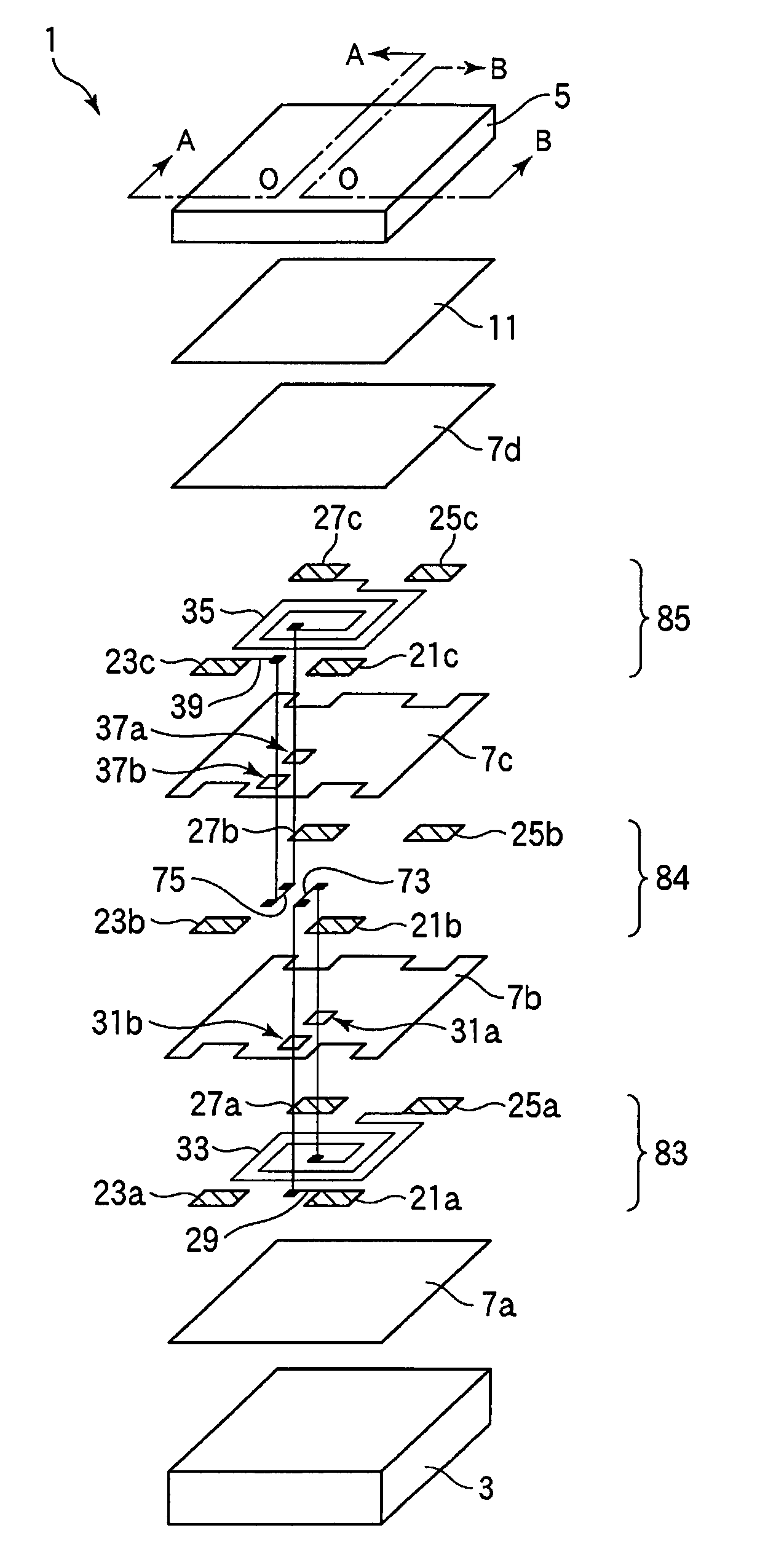
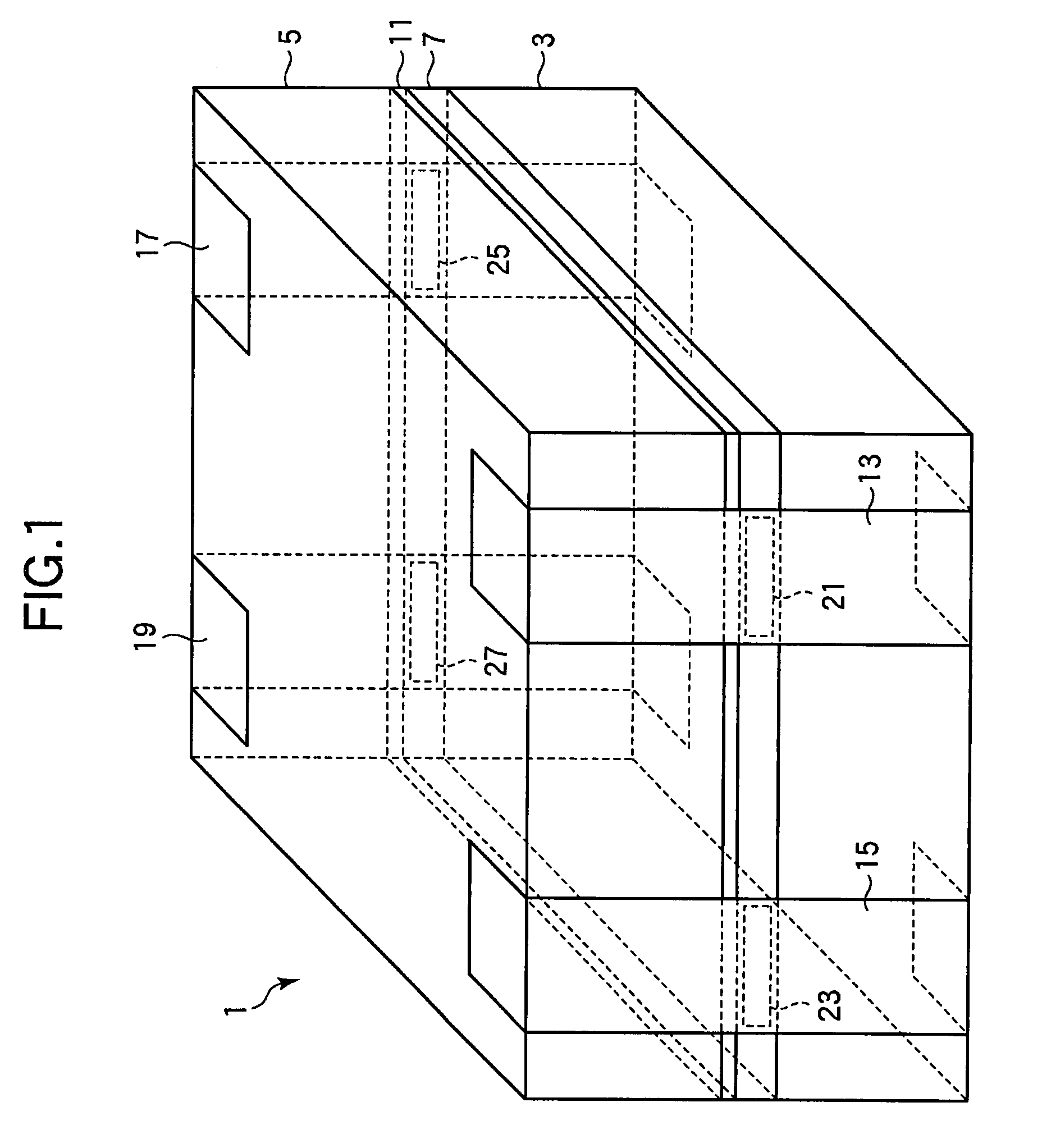
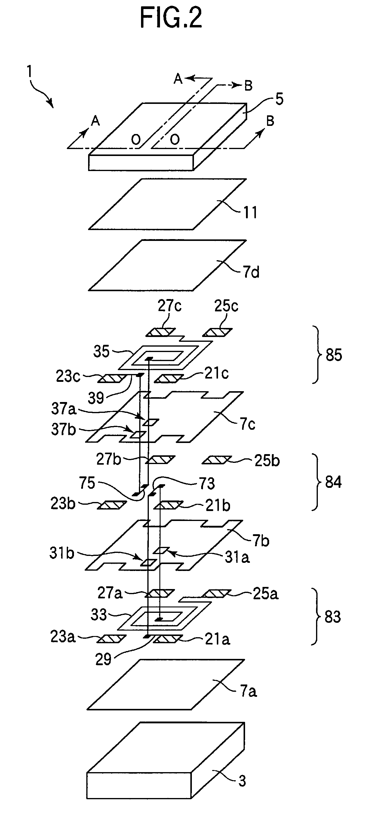
[0027]A coil component according to an embodiment of the invention will now be described with reference to FIGS. 1 to 6. A common mode filter for suppressing a common mode current which can cause electrostatic interference in a balanced transmission system will be described as an example of a coil component of the present embodiment. FIG. 1 is a perspective view of a common mode filter 1. In FIG. 1, hidden lines are indicated by broken lines.

[0028]As shown in FIG. 1, the common mode filter 1 has a rectangular parallelepiped outline which is formed by stacking thin films between two magnetic substrates 3 and 5 in the form of thin rectangular parallelepiped plates disposed to face each other. An insulation layer 7 and a bonding layer 11 are formed in the order listed between the magnetic substrates 3 and 5 using thin-film forming techniques. Internal electrode terminals 21, 23, 25, and 27 are formed in the vicinity of side surfaces of the insulation layer 7 such that they are exposed ...


PUM

PropertyMeasurementUnit
distanceaaaaaaaaaa
thicknessaaaaaaaaaa
distanceaaaaaaaaaa

Abstract

The invention relates to surface-mount type coil components having a mounting surface for mounting them on a printed circuit board or hybrid IC (HIC) and provides a low-cost coil component having a low direct-current resistance. A common mode filter includes a bridge conductor layer which has a bridge conductor one end of which is connected to one end of a lead wire and another end of which is connected to an inner circumferential end of a coil conductor and another bridge conductor one end of which is connected to one end of another lead wire and another end of which is connected to an inner circumferential end of another coil conductor, the bridge conductor layer being formed between two coil conductor layers with an insulation film interposed between the bridge conductor layer and each of the coil conductor layers.

Description

BACKGROUND OF THE INVENTION[0001]1. Field of the Invention[0002]The present invention relates to a surface-mount type coil component having a mount surface for mounting the same on a printed circuit board or a hybrid IC (HIC).[0003]2. Description of the Related Art[0004]Known coil components mounted on circuits in electronic apparatus such as personal computers and cellular phones include wire-wound type components provided by winding a copper wire around a ferrite core, multi-layer type components provided by forming a coil conductor pattern on a surface of a magnetic sheet made of ferrite and stacking such magnetic sheets one over another, and thin-film type components provided by forming insulation films and coil conductors constituted by metal thin films alternately using thin film forming techniques. Multi-layer type and thin-film type coil components can be easily provided with a small size.[0005]Known coil components include common mode filters for suppressing a common mode c...

Claims


Application Information

Patent Timeline
Patent Type & Authority Patents(United States)
IPC IPC(8): H01F5/00
CPCH01F17/0006H01F27/292H01F17/0013H03H2001/0092H01F27/323H01F27/027
Inventor NISHIKAWA, TOMONAGAITO, TOMOKAZUYOSHIDA, MAKOTOKAMIYAMA, HIROSHI
Owner TDK CORPARATION
Why Eureka
Try Eureka