
Multiple node network and communication method within the network

a multi-node network and communication method technology, applied in the field of multi-node network and communication method within the network, can solve the problems of large network time consumption, failure of arbitration, and failure to successfully arbitrate the contention

Active Publication Date: 2008-08-05
YAMAHA MARINE KK
View PDF41 Cites 20 Cited by
  • Summary
  • Abstract
  • Description
  • Claims
  • Application Information

AI Technical Summary

Benefits of technology

"The present invention provides an improved network and communication method that can quickly boot up and communicate with each other. The network includes a management node and multiple terminal nodes that communicate with the management node using a bus. The terminal nodes transfer frames to the management node with a discriminative code in the data field to avoid contention. The management node arbitrates any contention between the terminal nodes by comparing the identifier fields of the terminal nodes. The terminal nodes can also re-transfer the frame after a time delay to avoid simultaneous transfer of multiple frames. The communication method involves creating a frame with a discriminative number for each component of the system and transferring it to the management node from the terminal nodes. The method can also include calculating a time delay and delaying the transfer of the frames from the terminal nodes in contention."

Problems solved by technology

The comparison, however, does not successfully arbitrate the contention because the identifier of each drive node is the same as one another.
The arbitration thus fails.
Accordingly, the network requires a large amount of time to boot up.

Method used


Image

  • Multiple node network and communication method within the network
  • Multiple node network and communication method within the network
  • Multiple node network and communication method within the network

Examples


Embodiment Construction

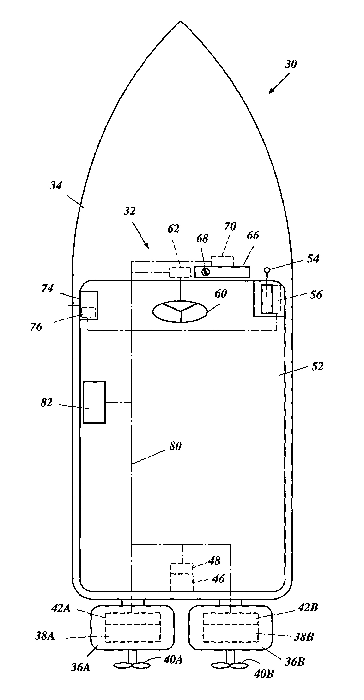
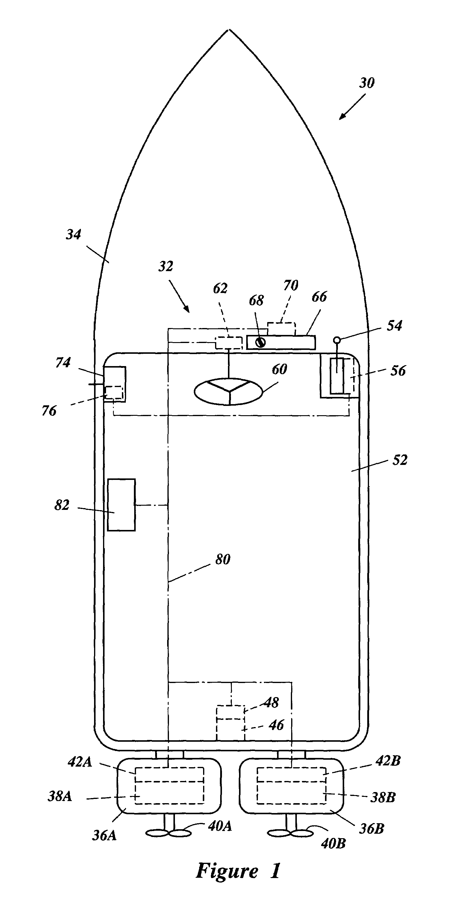
[0025]With reference to FIG. 1, a watercraft 30 and a controller area network (CAN) 32 for the watercraft 30 is described. The CAN 32 is one type of a local area network (LAN). While a network is described in connection with this particular type of network (i.e., the CAN 32) for the particular type of system (e.g., the watercraft 30), those of skill in the art will appreciate that the present invention may have utility in a wide range of applications for other types of networks that are used for other systems such as, for example, land vehicles, toys, game machines, factory control systems, building management systems or the like.

[0026]The watercraft 30 has a hull 34. At least one drive unit propels the bull 34. In the illustrated embodiment, a pair of outboard motors 36A, 36B preferably are mounted on a transom of the hull 34 as the drive units to propel the hull 34. Other marine drives such as, for example, stern drives can replace the outboard motors 36A, 36B. Each outboard motor...


PUM


Abstract

A multiple node network includes a plurality of terminal nodes. A management node manages the terminal nodes. A bus connects the respective terminal nodes and the management node to one another. The respective terminal nodes and the management node communicate with each other using a frame that includes at least an identifier field and a data field. The data field has a discriminative number. Each terminal node transfers the frame to the management node. A contention between the terminal nodes is arbitrated by comparing the respective identifier fields of the terminal nodes. When the arbitration fails, each terminal node repeatedly transfers the frame to the management node after a delay time that is unique for the particular terminal node and that is calculated based upon the discriminative number in the data field.

Description

PRIORITY INFORMATION[0001]The present application is based on and claims priority under 35 U.S.C. § 119 to Japanese Patent Application No. 2002-202032, filed on Jul. 11, 2002, the entire content of which is expressly incorporated by reference herein.BACKGROUND OF THE INVENTION[0002]1. Field of the Invention[0003]The present invention generally relates to a multiple node network and a communication method within the network. The present invention more particularly relates to a network having a plurality of terminal nodes and a management node that manages the terminal nodes and also to a communication method among the terminal nodes and the management node.[0004]2. Description of Related Art[0005]Computerized controls have become popular for various systems such as, for example, land vehicles and watercrafts in recent years. Components of the systems such as engines and navigation devices typically are connected with each other using a network. Such engines and navigation devices eac...

Claims


Application Information

Patent Timeline
Patent Type & Authority Patents(United States)
IPC IPC(8): H04L12/413B63H20/00H04L1/16H04L12/40H04L29/02H04L29/06H04L29/08H04L29/12
CPCH04L12/403H04L29/06H04L29/12254H04L61/2038H04L67/325H04L67/12H04L2012/40215H04L69/329H04L2012/40286H04L69/28H04L2012/40273H04L61/5038H04L67/62H04L9/40
Inventor OKUYAMA, TAKASHI
Owner YAMAHA MARINE KK
Learn More