Electric drive axle

a technology of drive axle and drive wheel, which is applied in the direction of electric propulsion mounting, transportation and packaging, gearing, etc., can solve the problem of not always desirable torque division between the drive wheels on each side of the differential

Inactive Publication Date: 2008-08-12
THE TIMKEN CO
View PDF25 Cites 27 Cited by
  • Summary
  • Abstract
  • Description
  • Claims
  • Application Information

AI Technical Summary

Problems solved by technology

However, an equal division of torque between the drive wheels on each side of a differential is not always desirable.

Method used


Image

  • Electric drive axle
  • Electric drive axle
  • Electric drive axle

Examples


Embodiment Construction

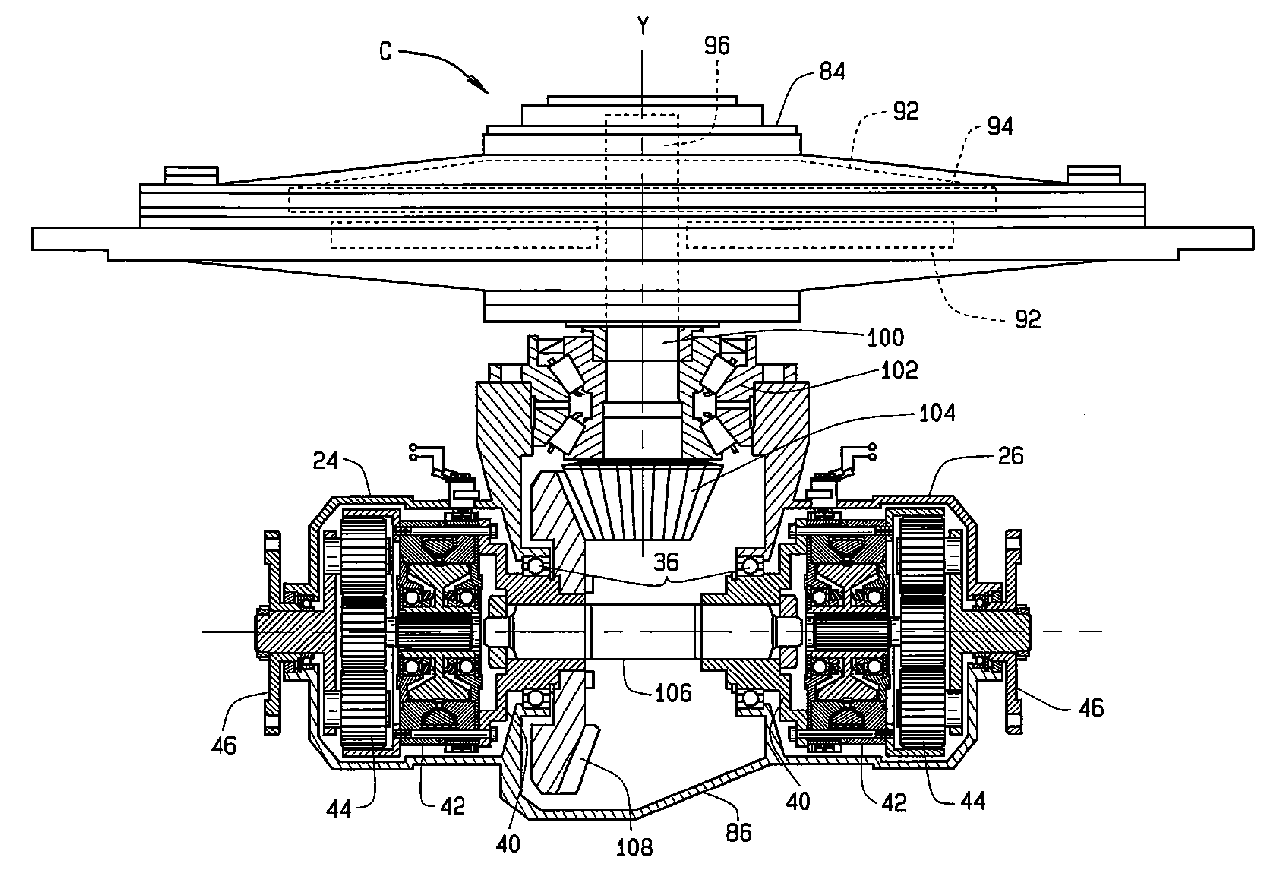
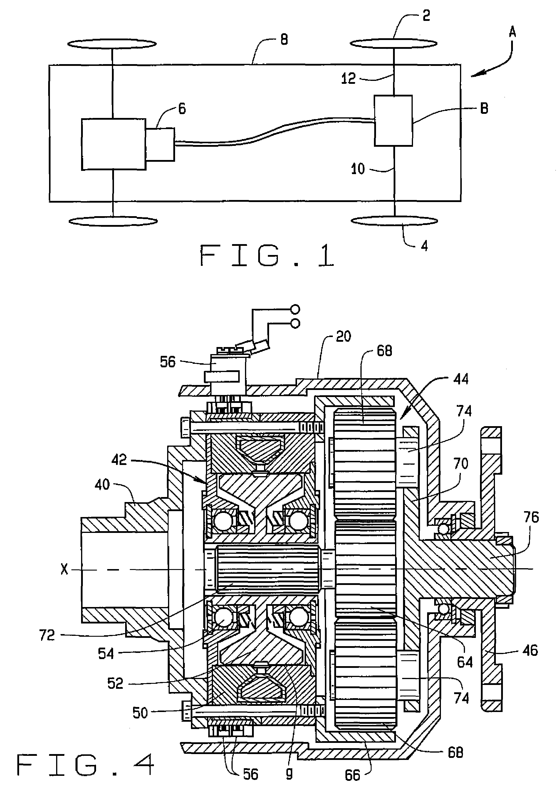
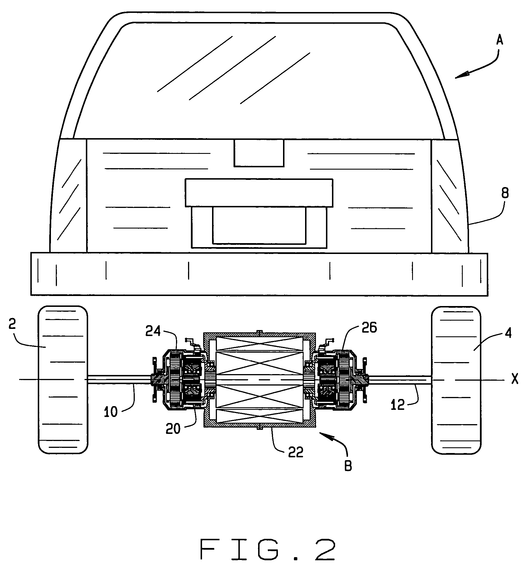
[0013]Referring now to the drawings, an automotive vehicle A (FIG. 1) has a left and right drive wheels 2 and 4, respectively, that are powered through an electric drive axle B. To this end, the vehicle A has a source 6 of electrical energy, which could be a generator powered by an internal combustion engine or a bank of batteries or even fuel cells. In any event, the energy source 6 and the drive axle B are mounted on a supporting structure 8, which could be a frame or a unified body, and the supporting structure 8 is in turn supported in part by the wheels 2 and 4. The drive axle B is coupled to the wheels 2 and 4 through left and right axle shafts 10 and 12. It is organized about an axis X and includes (FIG. 2) a housing 20, an electric motor 22, and left and right torque bias couplings 24 and 26, respectively. The motor 18 and couplings 24 and 26 are located within the housing 20.

[0014]The motor 22, which is of the radial flux construction, includes (FIG. 3) a stator 30 which is...


PUM


Abstract

An electric drive axle, which is located between and powers the left and right drive wheels of an automotive vehicle, includes an electric motor and left and right torque couplings. Torque developed by the motor transfers through the torque couplings to axle shafts which are connected to the drive wheels. Each torque coupling includes a magnetic particle clutch and a planetary set organized such that the current flowing through the electromagnet of the clutch controls the torque delivered through the coupler. The magnetic particle clutches also accommodate slippage so that the drive wheels may rotate at different angular velocities.

Description

CROSS-REFERENCE TO RELATED APPLICATIONS[0001]Not applicable.STATEMENT REGARDING FEDERALLY SPONSORED RESEARCH[0002]Not applicable.BACKGROUND OF THE INVENTION[0003]This invention relates in general to automotive vehicles and, more particularly, to an electrically-powered drive axle for an automotive vehicle.[0004]The typical automobile derives all the power required to propel it from an internal combustion engine which is coupled to left and right drive wheels through a transmission and differential. Indeed, the differential divides the torque produced by the engine evenly between the drive wheels to which it is coupled. Recently several automotive manufacturers have demonstrated an interest in automobiles that in one way or another utilize electric motors to propel the vehicles. But these vehicles still rely on differentials of conventional construction to divide torque between the left and right drive wheels and to accommodate variations in speed between the drive wheels, such as wh...

Claims


Application Information

Patent Timeline
Patent Type & Authority Patents(United States)
IPC IPC(8): B60K1/00B60L50/16
CPCB60K17/046B60K17/145F16H48/30F16H3/724B60K2001/001B60K17/04B60K17/16B60K17/02B60K7/00
Inventor GRADU, MIRCEA
Owner THE TIMKEN CO
Why Eureka
Try Eureka