Load lifting device

a technology of lifting device and load, which is applied in the direction of lifting device, lifting frame, transportation and packaging, etc., can solve the problems of variable arrangement, large drawback of lifting table, and large force required for lifting, and achieve the effect of great efficiency

Inactive Publication Date: 2008-08-19
COMAU SPA
View PDF13 Cites 47 Cited by
  • Summary
  • Abstract
  • Description
  • Claims
  • Application Information

AI Technical Summary

Benefits of technology

[0014]The object of the present invention is that of providing a lifting device of the type indicated at the beginning of the present description which is able to overcome the above mentioned drawbacks of the prior art and which in particular is able to exploit the force applied by the actuator with a great efficiency in order to obtain the lifting movement of the device.
[0015]A further object of the invention is that of providing a device of the above indicated type which has a relatively simple structure.
[0017]The structure and arrangement described in the foregoing actually solve the problem of transmitting the force applied by the actuator efficiently in order to obtain the lifting movement of the device.

Problems solved by technology

Lifting tables, however, have a huge drawback, which is implicit in their own way of operating.
Indeed, due to the specific configuration of their linkage, at the beginning of the lifting phase, starting from the closed condition of the pantograph linkage, the vertical movement is hindered by a number of unfavorable leverages, so that the force required for lifting is much greater than the weight to be lifted and is variable throughout the entire movement.
However, the arrangement shown in this document is not satisfactory, in particular because the above mentioned connecting element is subjected to a deflecting force during the lifting movement and therefore is not able to transmit the force applied by the actuator with a high efficiency.

Method used


Image

  • Load lifting device
  • Load lifting device
  • Load lifting device

Examples


Embodiment Construction

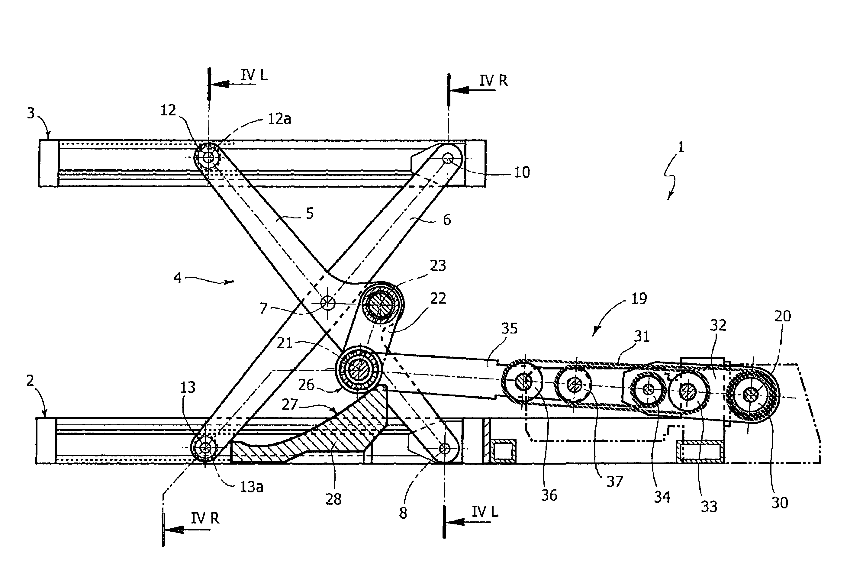
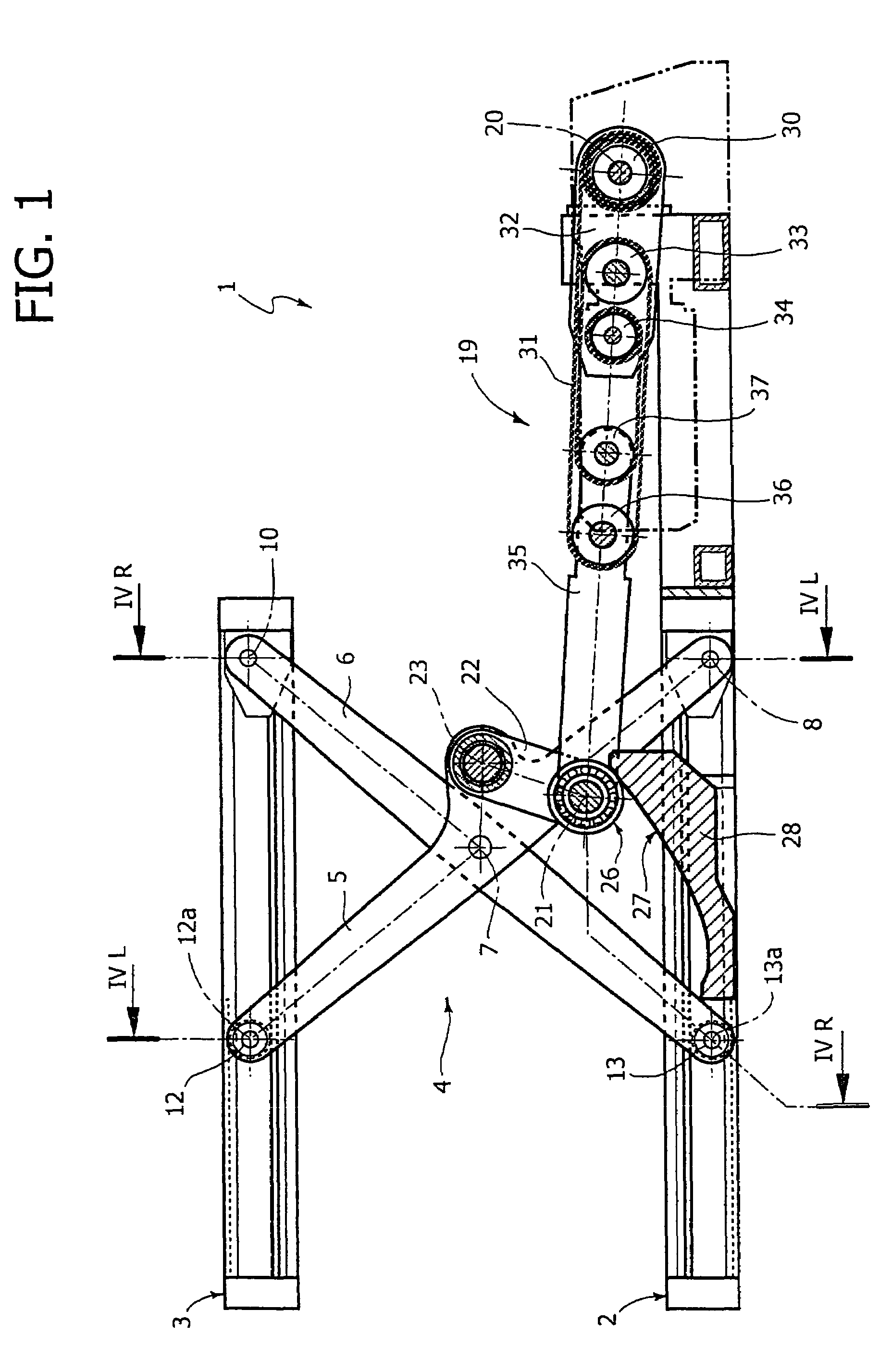
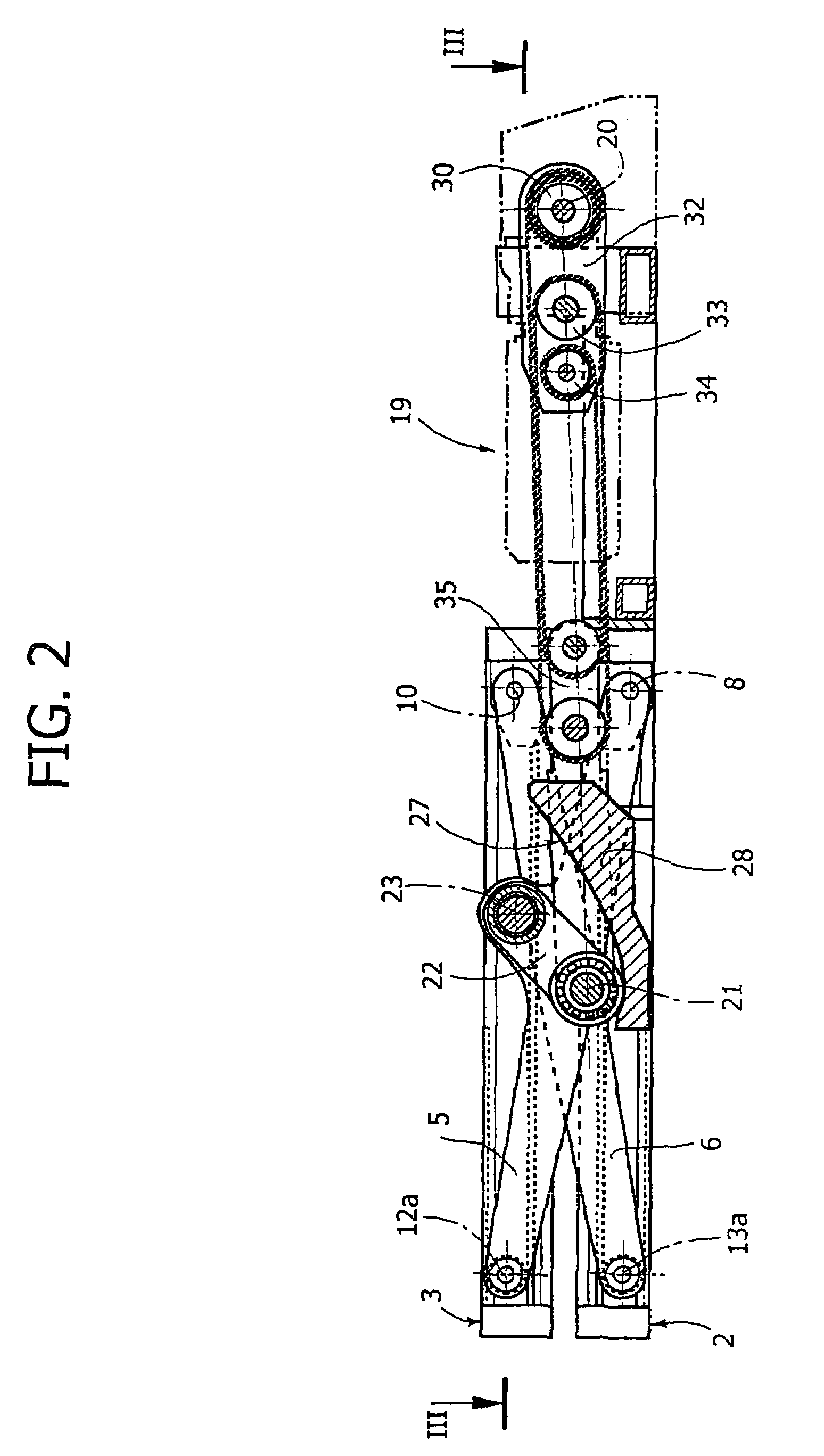
[0031]In the drawings, reference numeral 1 generally designates a lifting device of the type comprising a scissors-like linkage. Device 1 comprises a lower structure 2 and an upper structure 3 in form of a table or platform movable with respect to the lower structure 2 between a raised position, shown in FIG. 1, and a lowered position, shown in FIG. 2.

[0032]Table 3 is connected to the base structure 2 by means of a scissors-like linkage 4 which comprises two pairs of arms articulated to each other according to an X-shape and arranged in two vertical, parallel and spaced apart planes. Each pair of articulated arms comprises an arm 5 and an arm 6 articulated to each other around a horizontal axis 7. The arms 5 of the two pairs of articulated arms are arranged inside the two arms 6, as shown in FIG. 4.

[0033]Each of the two inner arms 5 has one of its ends articulated to the base structure 2 around an axis 8 which is horizontal and parallel to axis 7, by means of an articulation pin 9, ...


PUM


Abstract

A load lifting device includes a lower structure, an upper structure movable with respect to the lower structure between a lowered position and a raised position, a scissors-like pantograph, including at least two arms mutually articulated according to an X-shape, connecting the upper structure to the lower structure, and an actuator device controlling the position of a connecting element which connects the actuator to one arm of the pantograph and having a cam-following element cooperating with a fixed cam. The actuator is articulated to the connecting element around an axis which is located below the articulation axis of the connecting element to the arm of the pantograph, in such a way that, when the actuator is activated to cause the lifting movement of the device, the connecting element acts as a pushing strut subjected substantially to compression between the cam and the articulated arm. Preferably the actuator includes a hoist device with a belt, cord, or chain engaging a number of pulleys.

Description

BACKGROUND OF THE INVENTION[0001]The present invention relates to a lifting device of the type comprising:[0002]a lower structure,[0003]an upper structure movable with respect to the lower structure between a lowered position and a raised position,[0004]a linkage connecting the upper structure to the lower structure and including at least one articulated arm,[0005]an actuator operatively interposed between the lower structure and the linkage, for controlling the movements of the upper structure between its lowered position and its raised position,[0006]a connecting element between the actuator and the linkage, said connecting element being articulated to said arm of the linkage and being provided with a cam-follower element cooperating with a fixed cam.[0007]A device of the above indicated type is disclosed in JP 2000 238996.[0008]The invention relates in particular to a lifting table with a pantograph linkage of the scissors-type.[0009]As is known, pantograph-type lifting tables en...

Claims


Application Information

Patent Timeline
Patent Type & Authority Patents(United States)
IPC IPC(8): B66B9/02B66F3/22B66F7/06
CPCB66F7/065B66F3/02B66F3/46
Inventor GONZI, MARIOGONZI, FABRIZIO
Owner COMAU SPA
Why Eureka
Try Eureka