Sphero cylindrical eye refraction system using fluid focus electrostatically variable lenses

a technology of electrostatic variable lenses and cylindrical spheres, which is applied in the field of optical devices and systems, can solve the problems of large volume, easy wear and damage, and high cost of automatic refractors

Inactive Publication Date: 2008-08-19
AMO MFG USA INC
View PDF21 Cites 40 Cited by
  • Summary
  • Abstract
  • Description
  • Claims
  • Application Information

AI Technical Summary

Benefits of technology

[0008]The source may be configured to alter the at least one electrowetting potential so as to change a cylindrical power in response to a second input, and / or to alter the at least one electrowetting potential so that the one or more fluid / fluid interfaces vary in spherical power in response to a third input. Preferably, the spherical power may be varied throughout a range from at least about minus 20.0 diopters to at least about plus 20.0 diopters so as to accommodate substantially the full range of human eye spherical aberrations. Similarly, the apparatus will preferably have cylindrical powers which can be varied throughout a range from at least minus 6.0 diopters to at least plus 6.0 diopters, with the cylindrical orientation variable throughout a range of ate least about 90°; optionally being at least about 180°, so that the optical apparatus can compensate for substantially the full range of cylindrical aberrations in the human eye.
[0011]In many embodiments, first and second electrodes may be disposed along opposing sides of the first opening. Similarly, third and fourth electrodes may be disposed along opposing sides of the second opening, while fifth and sixth electrodes are disposed along opposing sides of the third opening. The electrodes along opposing sides of each opening may be coupled electrically so that a common electrowetting potential can be easily applied to both sides of each opening. Varying the electrowetting potential along both sides of the opening can controllably vary angles defined between the sides of the rectangular opening and the fluid / fluid interface within that opening, and / or vary positions of the fluid / fluid interface along the container wall adjacent the potential. This can be used to variably control the cylindrical power of the fluid / fluid interface, particularly where ends of the rectangular opening (connecting the opposed sides) are configured to maintain a 90° angle between the fluid / fluid interface and the end surface, such as by providing an end electrode at an appropriate electrowetting potential for each end of each rectangular opening.

Problems solved by technology

These moving components tend to make automatic refractors complex, bulky, susceptible to wear and damage, and quite expensive.

Method used


Image

  • Sphero cylindrical eye refraction system using fluid focus electrostatically variable lenses
  • Sphero cylindrical eye refraction system using fluid focus electrostatically variable lenses
  • Sphero cylindrical eye refraction system using fluid focus electrostatically variable lenses

Examples


Embodiment Construction

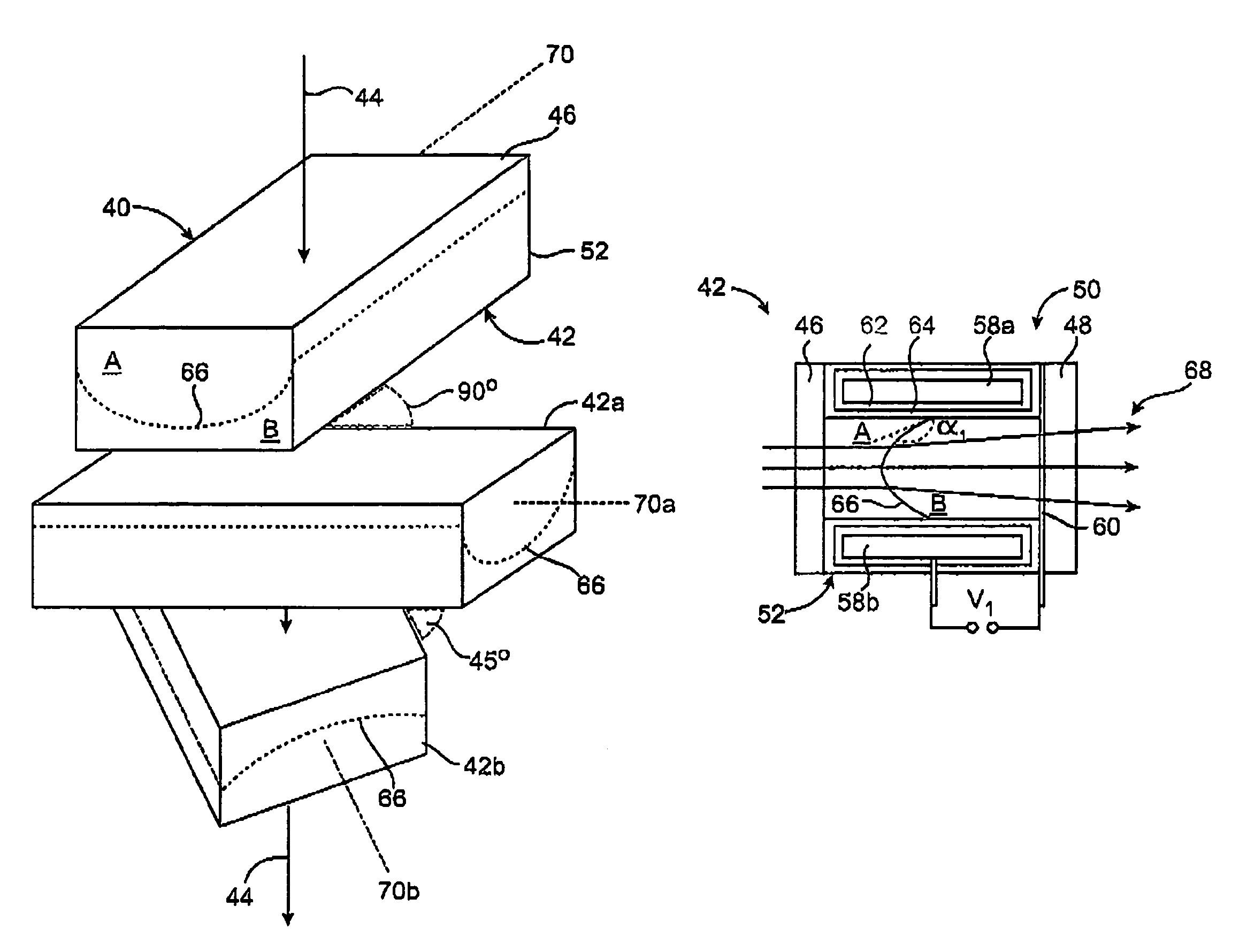
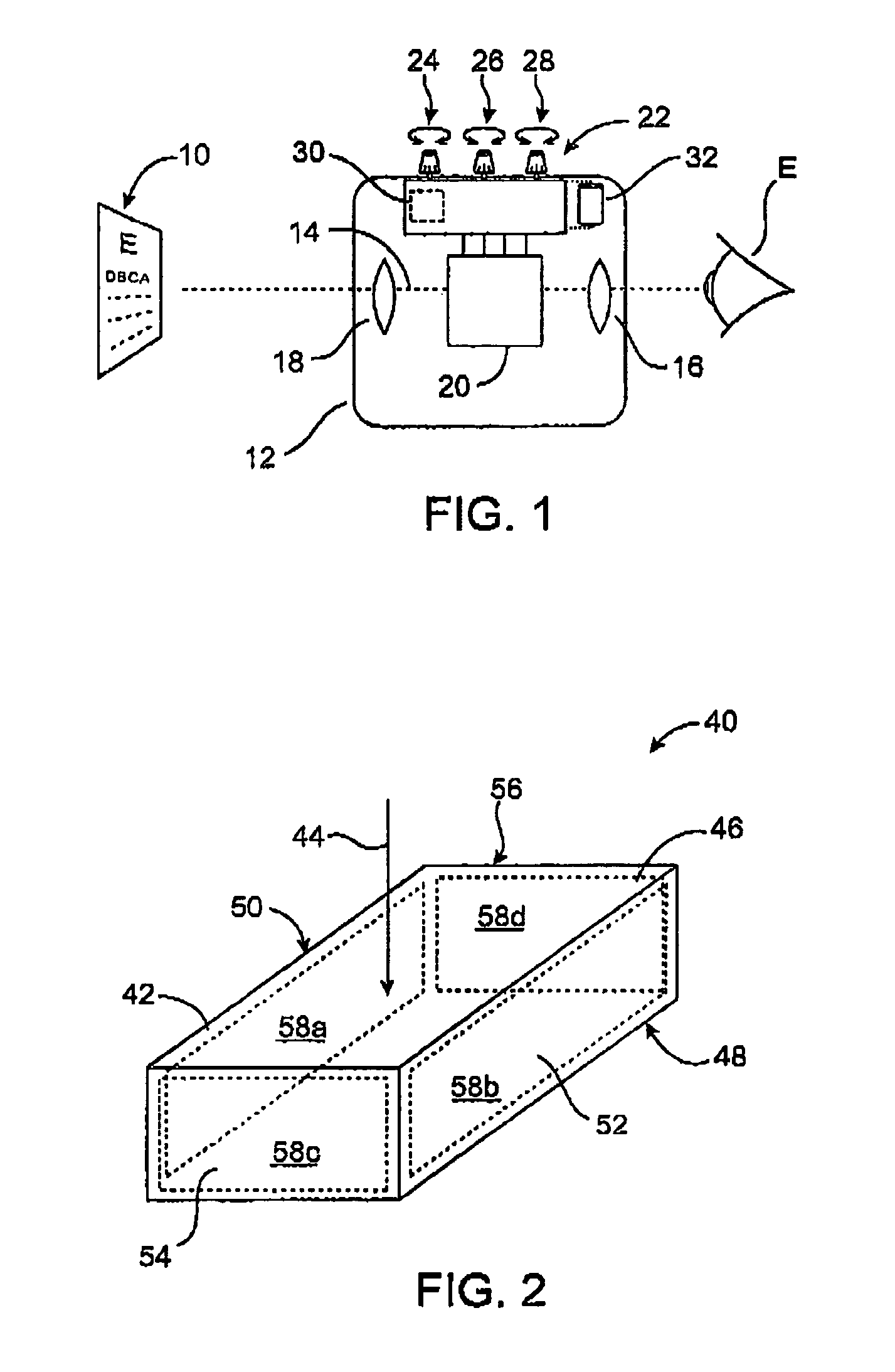
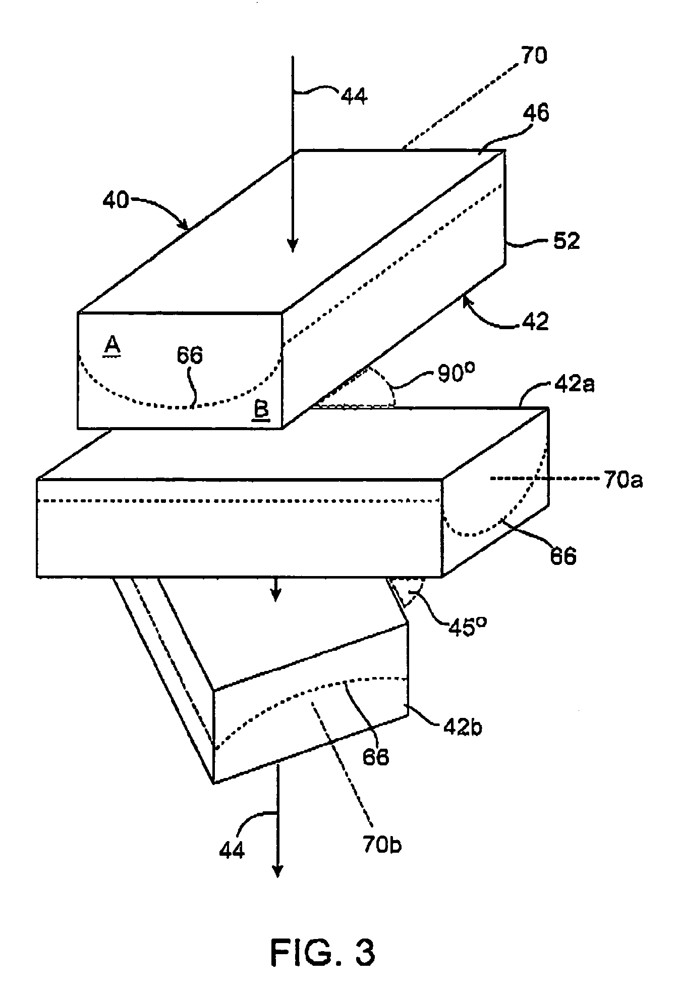
[0030]The present invention generally provides improved optical devices, systems, and methods. The invention often makes use of fluid lenses, particularly for varying a cylindrical axis or orientation, cylindrical power, spherical power, sphero-cylindrical characteristics, and / or other optical properties of a fluid / fluid interface. The relatively low cost, small size, light weight, and ease of manufacture of the fluid lenses described herein may allow common optical devices (such as binoculars, telescopes, cameras, microscopes, endoscopes, and even eye glasses) to compensate for cylindrical and / or spherical error of a user's eye by including these fluid lenses therein. While the devices and methods of the present invention are particularly well suited for measuring and / or compensating for standard aberrations of the human eye, they may also find applications in optical recording techniques, optical communications, optical signal processing and telecommunications, digital cameras, ca...


PUM


Abstract

Optical devices, systems, and methods can produce and / or measure cylindrical (as well as spherical) lens shapes throughout a range of both powers and cylindrical axes. Fluid focus lenses employ electrical potentials to vary the shape of a fluid / fluid interface between two immiscible fluids having differing indices of refractions by controlling localized angles between the interface and a surrounding container wall. Spherical power, cylindrical power, and cylindrical access alignment may be varied with no moving parts (other than the fluids).

Description

BACKGROUND OF THE INVENTION[0001]The present invention is generally related to optical devices, systems, and methods, and in one embodiment provides a fluid lens capable of being adjusted in spherical and / or cylindrical power so as to allow, for example, correction of refractive errors of the human eye.[0002]Refractive errors of the human eye are measured in a variety of ways, including both subjective and objective approaches. Subjective measurements of the eye may be made by placing corrective lenses or a corrective optical system before the eye and conducting a controlled test of the resulting corrected vision. These eye tests are commonly used to identify a sphero-cylindrical correction that provides improved vision to a subject while that subject is reviewing a suitable target image.[0003]When conducting subjective refraction measurements, a series of individual trial lenses may be positioned before the eye of the test subject. In many subjective refraction tests, the subject l...

Claims


Application Information

Patent Timeline
Patent Type & Authority Patents(United States)
IPC IPC(8): A61B3/02G02B1/06G02B3/12G02C7/02
CPCA61B3/0285G02B26/004G02B3/12G02B3/14
Inventor CAMPBELL, CHARLES E.
Owner AMO MFG USA INC
Why Eureka
Try Eureka