Conveying apparatus and recording apparatus having the same

a technology of conveying apparatus and recording apparatus, which is applied in the direction of electrographic process, instruments, transportation and packaging, etc., can solve the problems of insufficient attempts to use high-quality paper, inability to implement a synchronous feeding by feedback control driving using a plurality of dc motors in printing and conveying in the relatively long conveyance path, and inability to achieve high-quality paper. , to achieve the effect of eliminating the influence of the generated conveyance resistance, high accuracy and

Inactive Publication Date: 2008-08-19
CANON KK
View PDF31 Cites 24 Cited by
  • Summary
  • Abstract
  • Description
  • Claims
  • Application Information

AI Technical Summary

Benefits of technology

[0017]The present invention is directed to implementing a synchronized sheet conveyance with high accuracy by carrying out a driving control using a plurality of motors to eliminate an affect of a conveyance resistance generated in a conveyance path. In a recording apparatus, the present invention is directed to carrying out a conveyance of recording paper with high accuracy.
[0020]According to the above configurations, it is possible to minimize the affect of external disturbance which the conveyance roller disposed at the downstream side of the conveyance path receives due to the conveyance resistance in the conveyance path, by controlling driving of the conveyance roller disposed at the upstream side of the conveyance path. In addition, it is possible to achieve stabilization of the movement of recording paper due to the conveyance resistance.

Problems solved by technology

With regard to feeding from the upper cassette, efforts have been made so that both high-quality paper and ordinary paper can be used, however, with regard to feeding from the U-turn cassette feeding, enough attempt has not been made in order to use the high-quality paper.
In addition, there are some cases in which degradation of image quality is permitted to some extent.
However, in the printing and conveying operation, in which good accuracy is most demanded among operations of the inkjet recording apparatus, no attempt has been made to implement a synchronous feeding by feedback control driving using a plurality of DC motors in the printing and conveying in the relatively long conveyance path, such as U-turn conveyance and the like.
However, in a conventional U-turn conveyance and printing, an effect of the conveyance resistance generated when a sheet of strong stiffness is conveyed in the U-turn path cannot be overcome.
As a result, degradation of image quality occurs because a desired amount of sheet cannot be conveyed by the LF conveyance roller.
In addition, in a case where the U-turn conveyance path having a large diameter is employed, the size of the apparatus body becomes large, and accordingly, a manufacturing cost is increased.
Besides, the apparatus of a large size itself cannot be accepted by its user.
Thus, the conveyance resistance applied to the LF conveyance roller increases and results in decrease in the conveyance amount at the LF conveyance roller.
Thus, the conveyance resistance applied to the LF conveyance roller decreases and results in increase in the conveyance amount at the LF conveyance roller.
Further, there is much difference in the conveyance resistance between when both the U-turn conveyance roller and the LF conveyance roller convey the paper sheet and when only the LF conveyance roller conveys the paper sheet after the trailing edge of the sheet passes the nip of the U-turn conveyance roller.
Therefore, the conveyance amount by the LF conveyance roller varies correspondingly, which causes remarkable image unevenness.
Further, because the same form of conveyance is employed for both the paper sheet of strong stiffness and the paper sheet of weak stiffness, it is difficult to use both types of paper sheet in a manner suitable to both types.
However, in the intermittent feeding, a good and sufficient control cannot be achieved because the cost of the tension detection section is increased, and additionally the period of variance of the tension is short, and its variance is abrupt.
Thus, it becomes difficult to obtain an appropriate conveyance accuracy.
Further, in a case of simultaneously operating the DC motors, operation errors are relatively permitted even when there occurs difference in the operation of the motors.
The above problems have been getting more difficult to overcome under the situation in which printing on a thick high-quality printing paper with strong stiffness is demanded while high image quality printing has been recently developed, because of the effect of external force due to bending stiffness and the friction resistance of the printing paper.

Method used


Image

  • Conveying apparatus and recording apparatus having the same
  • Conveying apparatus and recording apparatus having the same
  • Conveying apparatus and recording apparatus having the same

Examples


first embodiment

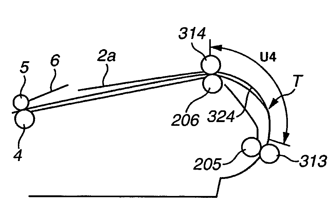
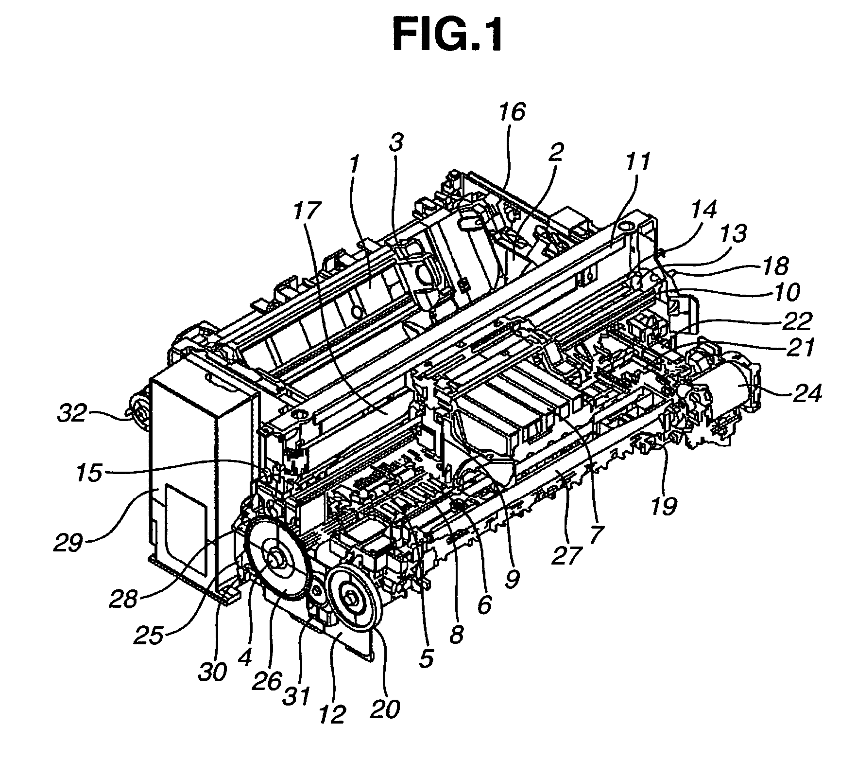
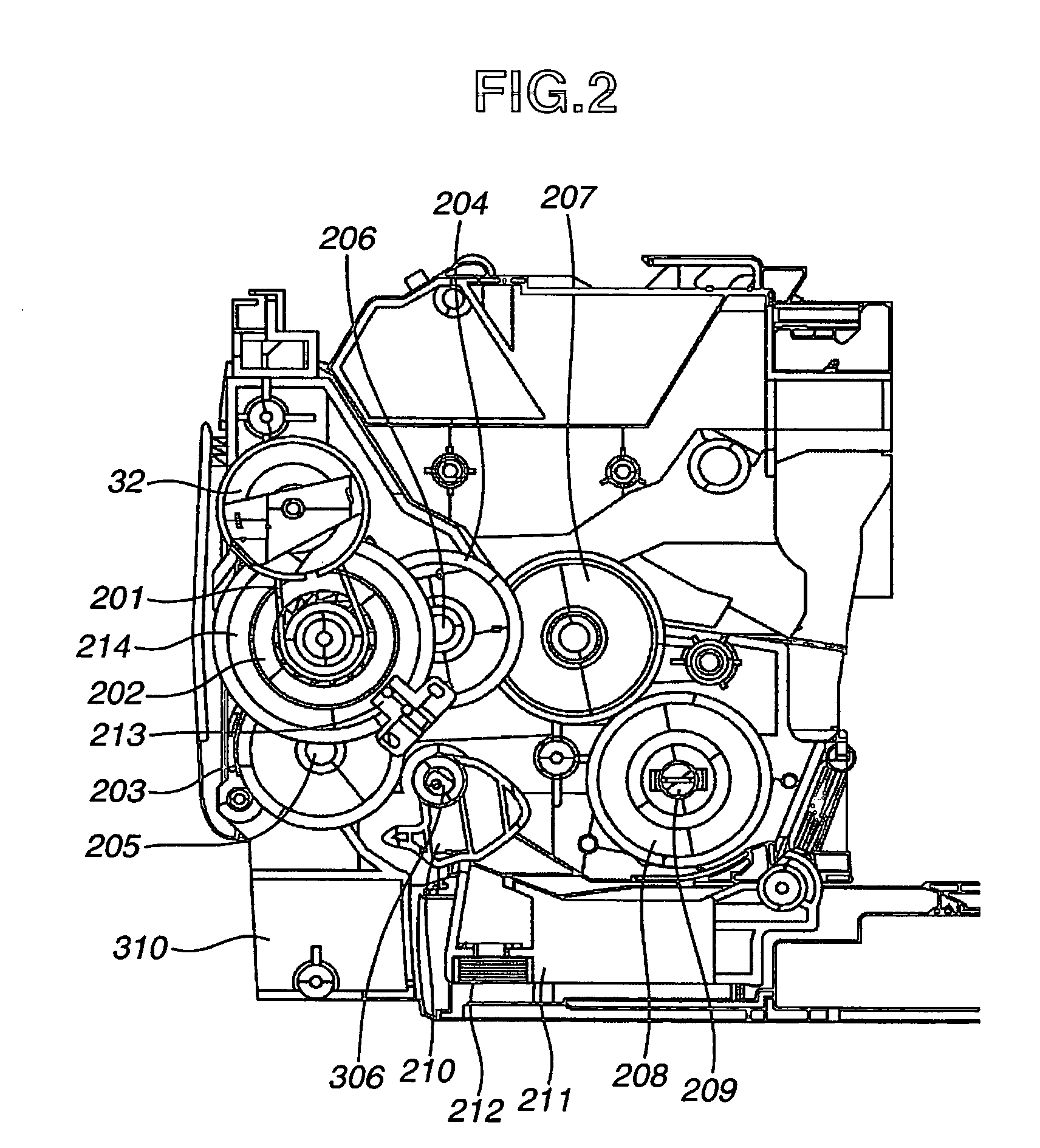
[0043]FIG. 1 is a perspective view showing a whole constitution of a recording apparatus in accordance with a first embodiment of the present invention. FIG. 2 is a section view of sheet conveyance driving system in the first embodiment of the present invention. FIG. 3 is a section view of a sheet conveyance system in the first embodiment of the present invention.

[0044]The recording apparatus is constituted by (A) an automatic sheet feed and conveyance unit, (B) a carriage unit, (C) a sheet discharge unit, and (D) a cleaning unit. In this regard, outline of these units is explained in order by referring to each of the items.

[0045](A) Automatic Sheet Feed Unit and Conveyance Unit

[0046]The automatic sheet feed and conveyance unit includes two automatic sheet feed sections. Hereafter, an upper automatic feed section is referred to as an ASF sheet feed section, and a lower automatic sheet feed section is referred to as a U-turn sheet feed and cassette sheet feed section.

[0047]A-1—ASF Sh...

second embodiment

[0166]A main constitution of the recording apparatus in a second embodiment of the present invention is identical to the constitution as explained in the first embodiment, and accordingly, explanation is omitted herein.

[0167]In the second embodiment, as a unit for recognizing the position of the trailing edge of the recording paper P, the sheet length from a printer driver is used. It is possible to grasp the position of the trailing edge of the recording paper P on the basis of the sheet length from the printer driver, the actually fed amount of conveyance, and a shape of the conveyance path which is previously determined. Thus, it becomes possible to appropriately set the parameter even in the region in which the trailing edge of the recording paper P exists at the upstream side of the second sheet position detection sensor lever 330 in the direction of conveyance. It is also possible to achieve a similar effect with a lower cost by eliminating the second sheet position detection ...


PUM


Abstract

A conveying apparatus which synchronously conveys a conveyed object includes a first conveyance roller disposed at a downstream side of a conveyance path for conveyance of the conveyed object and a second conveyance roller disposed at an upstream side of the conveyance path, a first driving unit and a second driving unit for independently driving the first conveyance roller and the second conveyance roller, respectively, and a control unit for performing feedback control of the first driving unit and the second driving unit on the basis of amounts of rotation of the first conveyance roller and the second conveyance roller, respectively. The control unit defines a setting of driving control for the second conveyance roller different from driving of the first conveyance roller.

Description

BACKGROUND OF THE INVENTION[0001]1. Field of the Invention[0002]The present invention relates to a conveying apparatus for conveying a conveyed object, and more particularly to control of conveyance of a recording medium in a recording apparatus for recording on the recording medium.[0003]2. Description of the Related Art[0004]In recent years, an inkjet recording apparatus has made a remarkable progress, and high image quality printing, high speed printing, and printing with lower operation noise have rapidly progressed. In addition, there has been notable growth in a number of users, and accordingly, the inkjet recording apparatus has been used in various ways. Conventionally, in order to achieve high image quality printing, it is preferable that a sheet is fed from an upper cassette, in which the bending of printing paper is reduced to a minimum. On the other hand, in order to stack a large amount of sheets of ordinary paper for printing, it is preferable that the sheet is fed fro...

Claims


Application Information

Patent Timeline
Patent Type & Authority Patents(United States)
IPC IPC(8): B65H5/06
CPCB41J13/0063B41J13/0027
Inventor SAITO, HIROYUKITAGUCHI, MOTOYUKI
Owner CANON KK
Why Eureka
Try Eureka