Distortion compensating amplifier

a distortion compensation and amplifier technology, applied in amplifier modifications, transmission monitoring, baseband system details, etc., can solve the problems of affecting the quality of communication of these channels, inconvenient cost and apparatus size, and unwanted wave on the antenna side of distortion compensation control

Inactive Publication Date: 2008-08-19
FUJITSU LTD
View PDF7 Cites 19 Cited by
  • Summary
  • Abstract
  • Description
  • Claims
  • Application Information

AI Technical Summary

Benefits of technology

[0019]Accordingly, an object of the present invention is to so arrange in that distortion compensation control can be carried out correctly even if a signal (an unwanted wave) from another service or from another system enters from the antenna side and mixes in with the feedback signal y(t).
[0020]Another object of the present invention is to so arrange it that a distortion compensation coefficient table can be prevented from shifting from optimum values even if a signal (an unwanted wave) from another service or from another system enters from the antenna side and mixes in with the feedback signal y(t), the end result being that the distortion compensation characteristic will not be degraded.
[0027]In accordance with the distortion compensating amplifier of the second aspect of the invention, an unwanted-wave threshold value for suspending updating of the distortion compensation coefficient table is changed in accordance with the level of the transmit signal. For example, signal power of a distortion component conforming to the power of the transmit signal is measured in advance and a signal having a level greater than the measured level to a certain extent is stored for every transmit-signal level as a threshold value for detecting unwanted waves. When an unwanted wave is detected, a threshold value corresponding to the transmission level is read out. If the threshold value is exceeded, it is determined that an unwanted wave has been detected and updating of the distortion compensation coefficients is suspended. If this arrangement is adopted, the threshold value will increase when the power of the transmit signal increases. This makes it possible to prevent the updating of distortion compensation coefficients from being suspended owing to a low unwanted-wave level when the transmission power is high.
[0028]In accordance with the distortion compensating amplifier of the third aspect of the invention, it is so arranged that the feedback signal and unwanted-wave signal are input to level detecting means selectively. As a result, the level of an unwanted wave can be detected accurately without being affected by the level of the transmit signal and control for suspending updating of the distortion compensation coefficient table can be performed correctly based upon the level of the unwanted wave.
[0029]In accordance with the distortion compensating amplifier of the fourth aspect of the invention, dedicated means for detecting the level of an unwanted-wave signal is provided. This makes it possible to detect the level of an unwanted wave accurately at all times and to perform control for suspending updating of the distortion compensation coefficient table correctly based upon the level of the unwanted wave.

Problems solved by technology

Such leakage power constitutes noise in other channels and degrades the quality of communication of these channels.
However, this necessitates an amplifier having a performance higher than that actually needed and therefore is inconvenient in terms of cost and apparatus size.
A signal from another service or a signal of another system enters from the antenna side is an unwanted wave in distortion compensation control.
If an unwanted wave thus mixes in with the feedback signal, the proper error e(t) cannot be output and the distortion compensation characteristic deteriorates.
With the conventional method, however, an unwanted wave is regarded as distortion-component power, the distortion-component power cannot be detected correctly, an erroneous adjustment of delay time is made, the distortion compensation coefficient table shifts from the optimum values and the distortion compensation characteristic deteriorates.

Method used


Image

  • Distortion compensating amplifier
  • Distortion compensating amplifier
  • Distortion compensating amplifier

Examples


first embodiment

(B) First Embodiment

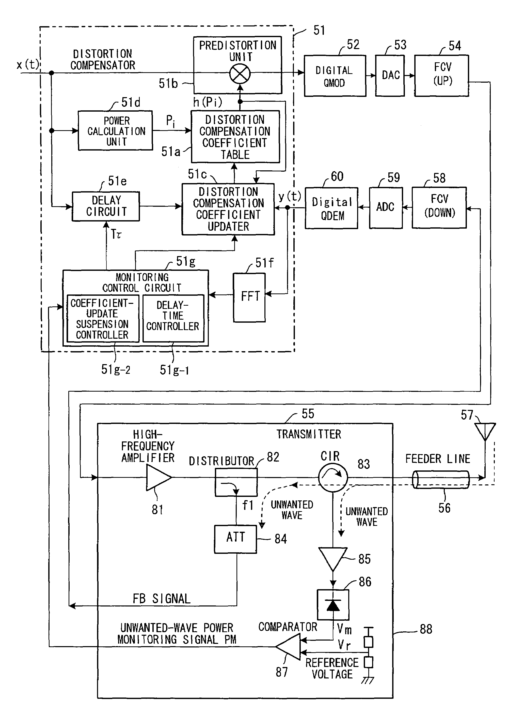
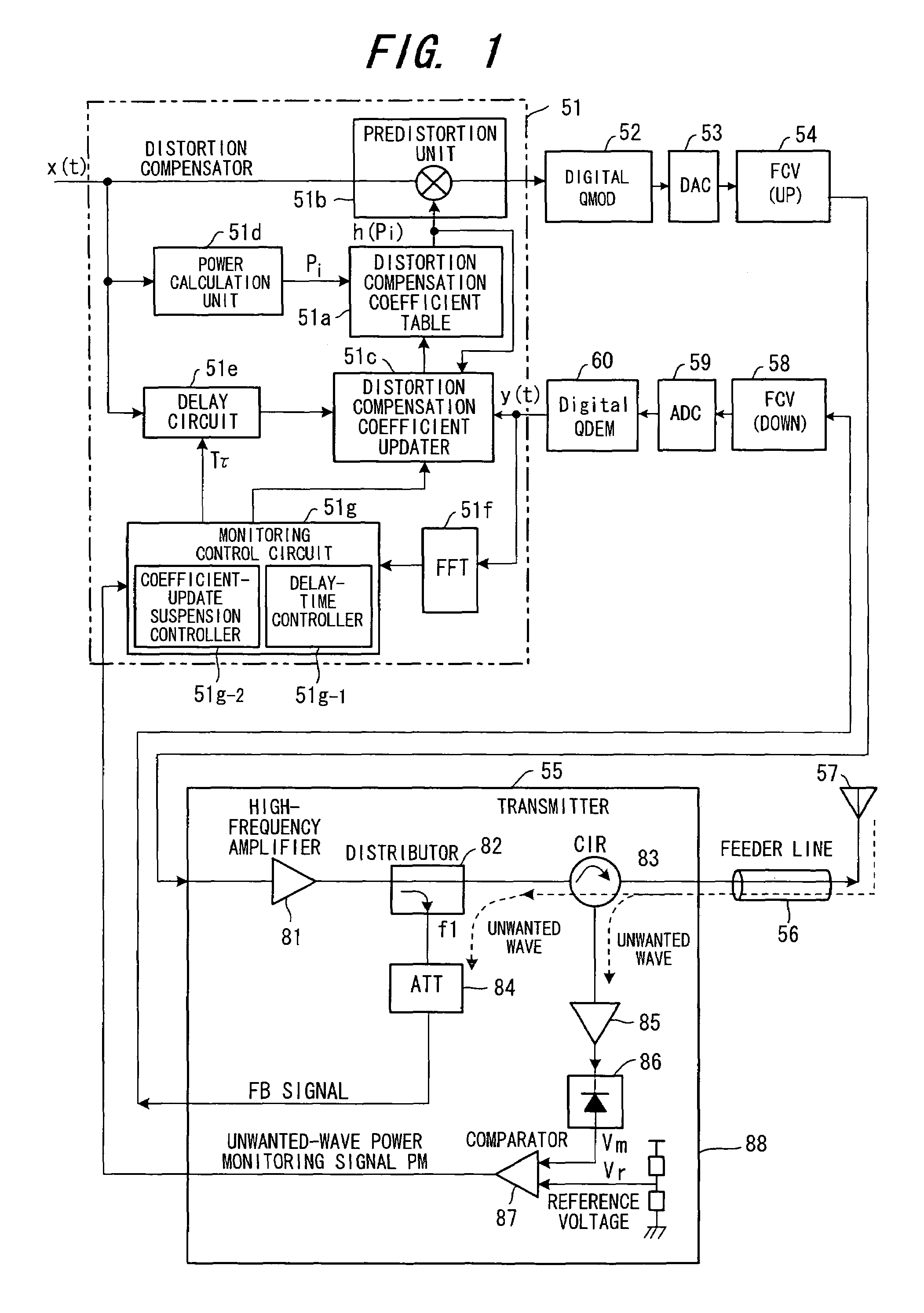
[0047]FIG. 1 is a block diagram illustrating a distortion compensating amplifier according to a first embodiment having a digital distortion compensating function. The distortion compensating amplifier includes a distortion compensator 51, a distortion compensation coefficient memory (distortion compensation coefficient table) 51a, a predistortion unit 51b, a distortion compensation coefficient updater 51c, a power calculation unit 51d, a delay circuit 51e, an FFT (Fast-Fourier Transform) unit 51f and a monitoring control circuit 51g.

[0048]The distortion compensation coefficient table 51a stores distortion compensation coefficients h(pi) (i=0˜1023) conforming to power levels pi of the transmit signal x(t), and the predistortion unit 51b subjects the transmit signal to distortion compensation processing using a distortion compensation coefficient h(pi) that is in conformity with the power level of the transmit signal. The distortion compensation coefficient updat...

second embodiment

(C) Second Embodiment

[0063]FIG. 4 is a block diagram illustrating a distortion compensating amplifier according to a second embodiment having a digital distortion compensating function. Components identical with those of the first embodiment shown in FIG. 1 are designated by like reference characters. This embodiment differs in that (1) the comparator 87 and reference-voltage setting unit 88 are deleted from the transmitter 55 and a signal obtained by rectifying the unwanted-wave signal is input to the distortion compensator 51; (2) the distortion compensator 51 is provided with an AD converter 51h, whereby the rectified unwanted-wave signal is converted to digital data and the digital data is input to the coefficient-update suspension controller 51g-2 of the monitoring control circuit 51g; (3) the transmit-signal power pi is input to the coefficient-update suspension controller 51g-2; and (4) the coefficient-update suspension controller 51g-2 executes control for suspending coeffic...

third embodiment

(D) Third Embodiment

[0073]FIG. 6 is a block diagram illustrating a distortion compensating amplifier according to a third embodiment having a digital distortion compensating function. Components identical with those of the first embodiment shown in FIG. 1 are designated by like reference characters. This embodiment differs structurally in that the transmitter 55 is provided with a signal changeover unit 89 so that the high-frequency amplified signal output from the high-frequency amplifier 81 and an unwanted-wave signal output from the amplifier 85 are input to the distortion compensation coefficient updater 51c and FFT unit 51f selectively via the frequency converter 58, AD converter 59 and digital demodulator 60.

[0074]FIG. 7 is a flowchart of control processing by the monitoring control circuit 51g according to the third embodiment.

[0075]The monitoring control circuit 51g generates a switch signal SW at a predetermined period, thereby causing the signal changeover unit 89 to alter...


PUM


Abstract

Disclosed is a distortion compensating amplifier having a distortion compensator for compensating for distortion of an amplifier by updating distortion compensation coefficients so as to null a difference between a transmit signal and a feedback signal, and subjecting the transmit signal to distortion compensation processing using the distortion compensation coefficients, an amplifier for amplifying the transmit signal, which has undergone distortion compensation, in order to transmit the signal from an antenna, and a feedback unit for inputting an output signal from the amplifier to a distortion compensation coefficient updater in the distortion compensator as the feedback signal. Whether the level of an unwanted-wave signal that penetrates the amplifier from space via an antenna is greater than a set level is monitored. If the level of the unwanted-wave signal is above the set level, processing for updating distortion compensation coefficients is suspended. If the level of the unwanted-wave signal is below the set level, then processing for updating distortion compensation coefficients is resumed.

Description

BACKGROUND OF THE INVENTION[0001]This invention relates to a distortion compensating amplifier and, more particularly, to a distortion compensating amplifier for monitoring input of undesired waves from an antenna and exercising control so as to halt updating of a distortion compensation table in accordance with the level of an undesired-wave input, thereby improving the distortion compensation characteristic at the time of an undesired-wave input.[0002]In wireless communications in recent years, there is growing use of high-efficiency transmission using digital techniques. In instances where multilevel phase modulation is applied to wireless communications, a vital technique is one which can suppress non-linear distortion by linearizing the amplification characteristic of the power amplifier on the transmitting side and reduce the leakage of power between adjacent channels. Also essential is a technique which compensates for the occurrence of distortion that arises when an attempt ...

Claims


Application Information

Patent Timeline
Patent Type & Authority Patents(United States)
IPC IPC(8): H04B1/04H03F1/32H04L27/36
CPCH03F1/3247H03F1/3294H04L27/368H03F2201/3227H03F2201/3233H03F2200/465
Inventor SASAKI, TAKAOSHAKO, HIDEHARUMIYAMOTO, HIROMI
Owner FUJITSU LTD
Why Eureka
Try Eureka