Distortion compensator

a technology of distortion compensation and conductor, which is applied in the field of distortion compensation, can solve the problems of extreme difficulty in actual practice to detect the power, etc. of individual frequency band signals, and conduct distortion compensation, and achieve the effect of reducing the effect of frequency characteristics

Inactive Publication Date: 2006-11-28
KOKUSA ELECTRIC CO LTD
View PDF19 Cites 37 Cited by
  • Summary
  • Abstract
  • Description
  • Claims
  • Application Information

AI Technical Summary

Benefits of technology

[0105]The graphs of FIGS. 11(a) to 11(d) show examples of AM-AM conversion-related inverse distortion characteristics regarding functions that conduct distortion compensation of mutually different divided frequency bands f1, f2, f3, fn (where n is 4 or greater; and f1–fn indicate the center frequencies of the divided frequency bands). The horizontal axes of the graphs in FIGS. 11(a) to 11(d) represent the level of the total power of the transmit signal to be amplified and the vertical axes represent amplitude control amount. As shown by these graphs, a different distortion compensation characteristic (inverse distortion characteristic) is used for each frequency band f1, f2, f3, fn, namely, the distortion compensation characteristic us

Problems solved by technology

When a signal to be amplified contains signals in multiple frequency bands, it is extremely difficult in actual practice to detect the

Method used


Image

  • Distortion compensator
  • Distortion compensator
  • Distortion compensator

Examples


first embodiment

[0133]An amplifier device incorporating the present invention will now be explained.

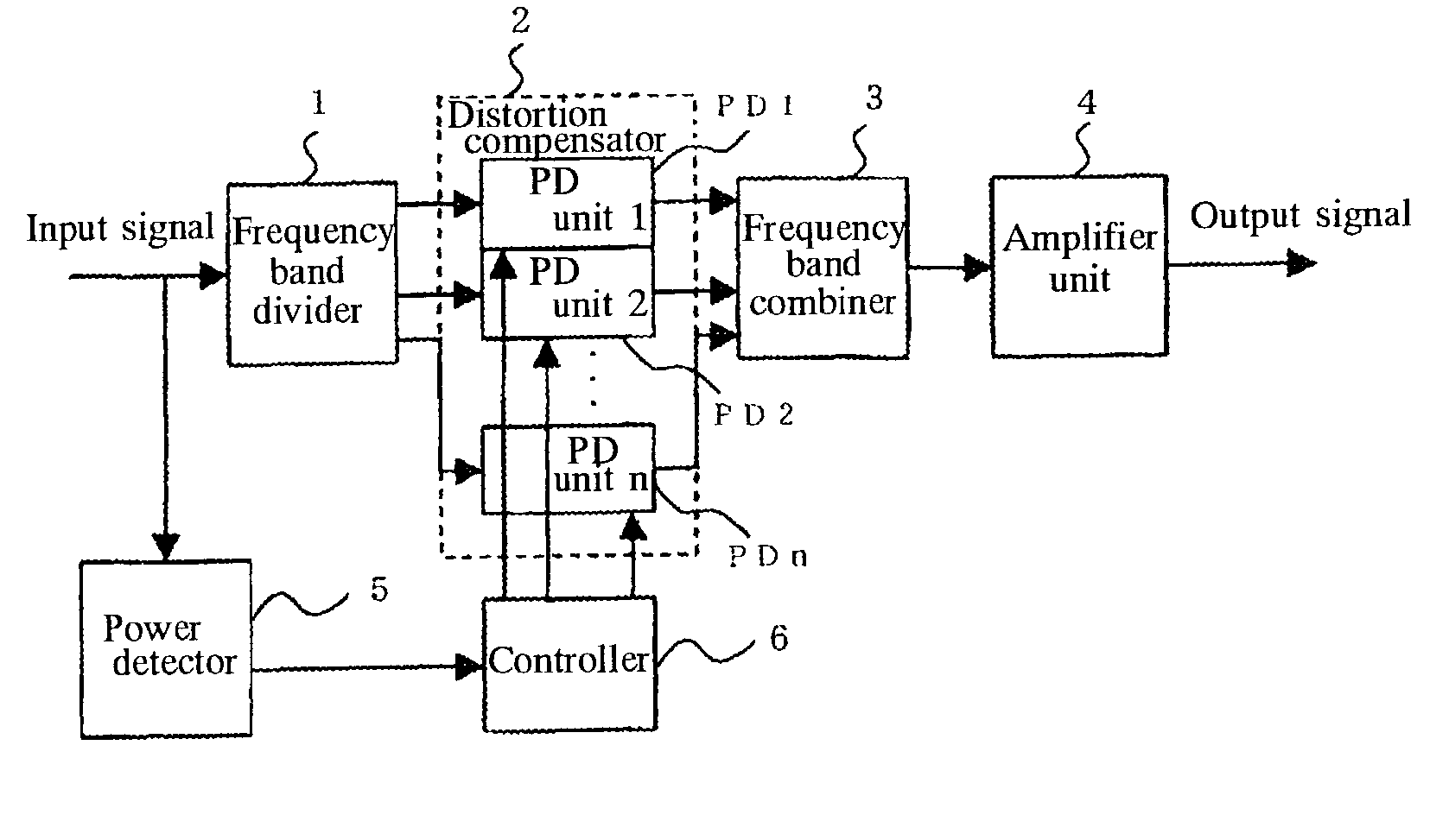
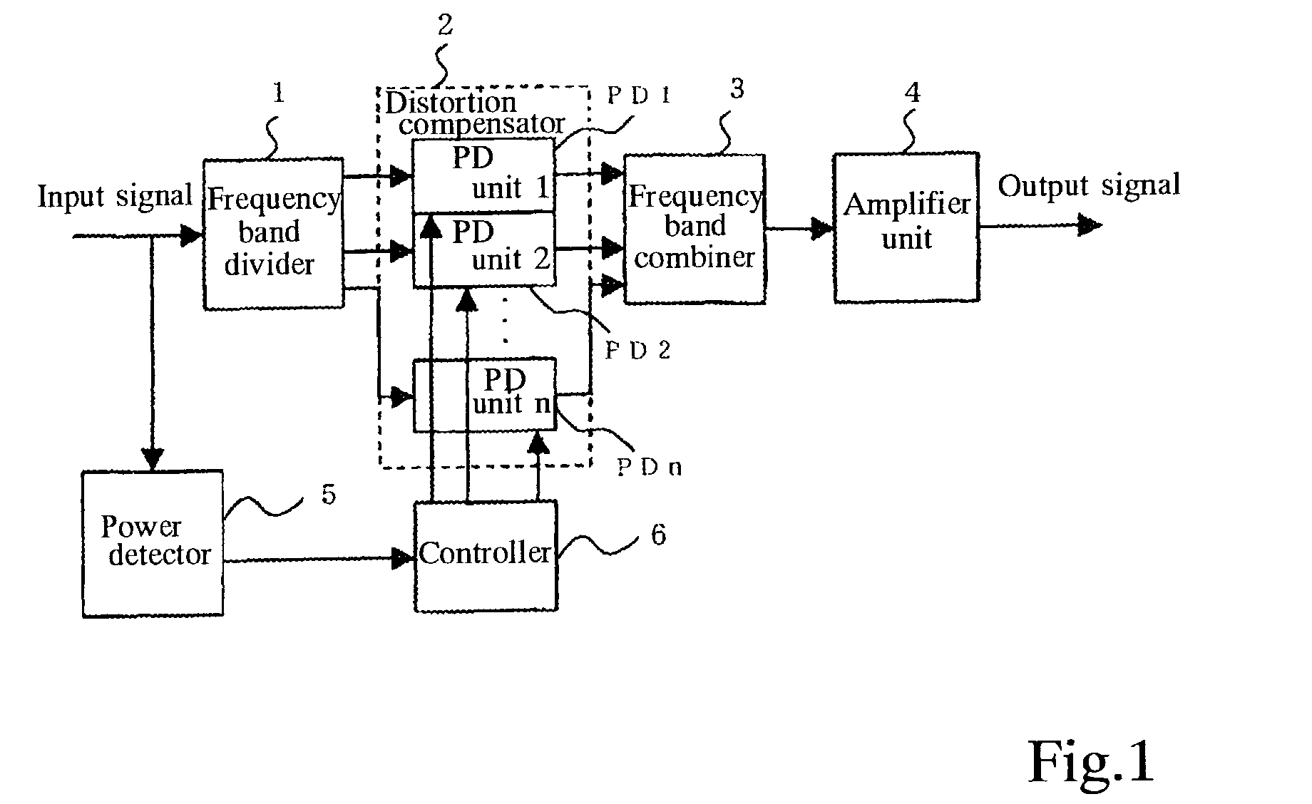
[0134]FIG. 1 is a block diagram showing the configuration of the amplifier device. The amplifier device comprises a frequency band divider 1, a distortion compensator 2 having n number of predistortion (PD) units PD1–PDn, a frequency band combiner 3, an amplifier unit 4, a power detector 5 and a controller 6.

[0135]In this embodiment, the multicarrier transmit signal to be amplified is input to the frequency band divider 1 and the power detector 5.

[0136]The frequency band divider 1 divides the input transmit signal into signals of n number of frequency bands f1–fn (where f1–fn indicate the center frequencies of the divided frequency bands: hereinafter the same). The signals of the divided frequency bands f1–fn are output to the predistortion units PD1–PDn corresponding to the frequency bands f1–fn. The frequency band divider 1 is constituted using band pass filters for extracting the signals of the fr...

second embodiment

[0147]An amplifier device incorporating the present invention will now be explained.

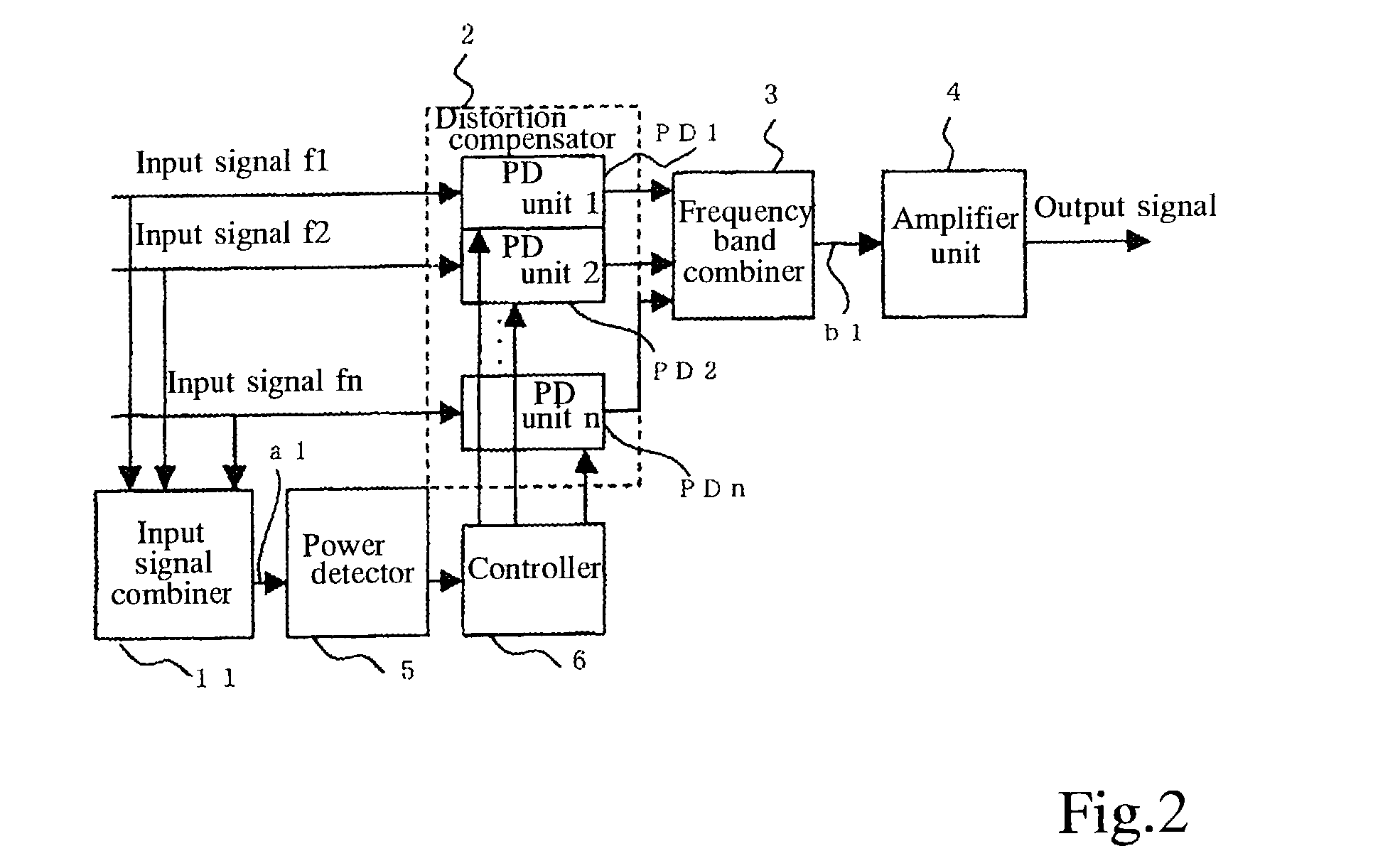
[0148]FIG. 2 is a block diagram showing the configuration of the amplifier device. As constituents having the same functions as their counterparts in the first embodiment shown in FIG. 1, the amplifier device of this embodiment comprises a distortion compensator 2 having multiple predistortion units PD1–PDn, a frequency band combiner 3, an amplifier unit 4, a power detector 5 and a controller 6. It is further provided with an input signal combiner 11. The amplifier device of this embodiment is not provided with the function of the frequency band divider 1 of the first embodiment shown in FIG. 1. For convenience of explanation, constituent elements having the same functions as ones of the first embodiment shown in FIG. 1 are assigned the same reference symbols as those shown in FIG. 1. The reference symbols a1 and b1 in FIG. 2 will be used to explain another embodiment discussed later.

[0149]In the amp...

third embodiment

[0155]An amplifier device incorporating the present invention will now be explained.

[0156]FIG. 3 is a block diagram showing the configuration of the amplifier device. As constituents having the same functions as their counterparts in the first embodiment shown in FIG. 1, the amplifier device of this embodiment comprises a frequency band divider 1, a distortion compensator 2 having multiple predistortion units PD1–PDn, a frequency band combiner 3, an amplifier unit 4 and a power detector 5. It is further provided with a demodulator 12 and a controller 13 having feedback control capability. For convenience of explanation, constituent elements having the same functions as ones of the first embodiment shown in FIG. 1 are assigned the same reference symbols as those shown in FIG. 1.

[0157]In this embodiment, the multicarrier transmit signal to be amplified is input to the frequency band divider 1, the power detector 5 and the controller 13.

[0158]Part of the signal output by the amplifier ...


PUM


Abstract

A distortion compensator for compensating for distortion produced in an amplifier that amplifies a signal includes a signal level detector for detecting a level of a signal to be amplified and a distortion compensator for conducting distortion compensation based on the detection result separately for each frequency band signal of multiple frequency band signals contained in the signal to be amplified. The distortion compensator improves distortion compensation performance by reducing the effect of frequency characteristics that restrict the distortion compensation performance limit.

Description

BACKGROUND OF THE INVENTION[0001]1. Field of the Invention[0002]This invention relates to a distortion compensator for correcting distortion occurring in an amplifier that amplifies transmit signals composed of different frequency carrier signals, an amplifier device equipped with the distortion compensator, a base station equipped with the amplifier device and a relay amplifier station equipped with the distortion compensator. This invention relates particularly to a technology that provides a distortion compensator appropriate for use with carrier signals having mutually different frequencies for improving accuracy of distortion compensation by reducing the effect of frequency characteristics.[0003]2. Description of the Prior Art[0004]In a mobile telecommunications system adopting wideband code-division multiple access (W-CDMA) technology, the base station (CDMA base station) is required to wirelessly transmit signals to reach CDMA mobile stations at remote physical locations. The...

Claims


Application Information

Patent Timeline
IPC IPC(8): H04L25/03H04B1/04H03F1/32H04J1/00H04L5/06
CPCH03F1/3247H03F1/3252H04L5/06
Inventor HONGO, NAOKIOKUBO, YOICHISUTO, MASAKIHORAGUCHI, MASATOTAKADA, TOSHIO
Owner KOKUSA ELECTRIC CO LTD
Why Eureka
Try Eureka