Robot controller

a robot controller and controller technology, applied in the field of robot controllers, can solve problems such as complication of system, data transfer wait time generation, and increase in the number of bus wiring lines

Active Publication Date: 2008-08-19
PANASONIC CORP
View PDF15 Cites 79 Cited by
  • Summary
  • Abstract
  • Description
  • Claims
  • Application Information

AI Technical Summary

Problems solved by technology

However, the conventional structure causes an issue that a data transfer wait time is generated due to the conflict of the bus failing in securing the real-time performance if it is attempted to take in a plurality of images or high-definition images by a plurality of imaging devices and handle a large amount of data for the achievement of further advanced intelligence.
Providing a bus exclusive for image transfer or providing a bus exclusive for connections among the means to prevent the above issue causes the complication of the system like an increase in the number of bus wiring lines and so on, and this is also disadvantageous in terms of the extendibility of the system.

Method used


Image

  • Robot controller
  • Robot controller
  • Robot controller

Examples


first embodiment

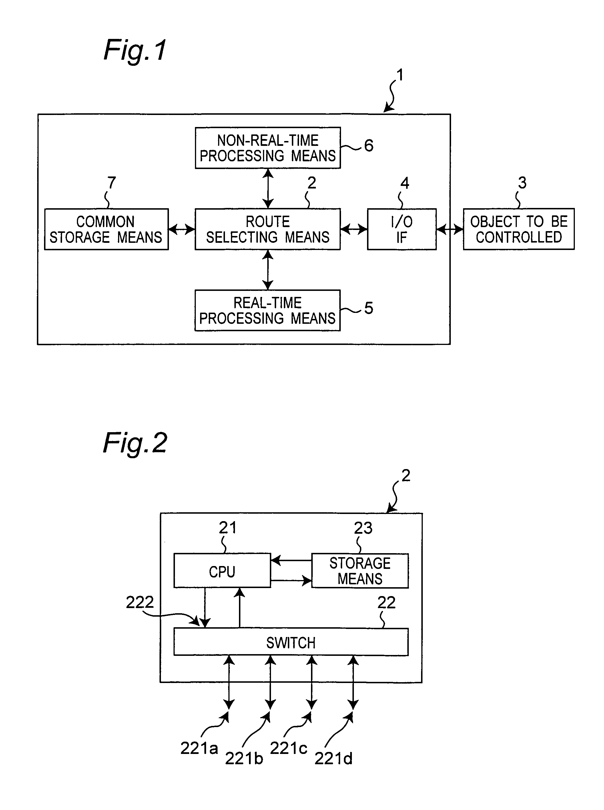
[0073]FIG. 1 is a view showing the construction of a robot controller 1 of the first embodiment of the present invention. In FIG. 1, the reference numeral 2 denotes a route selecting means for changing the route of digital signals in the robot controller 1. The route selecting means 2 is connected to: an input / output interface 4 connected to an object 3 to be controlled of the robot controller 1 of the present embodiment to output a command to the object 3 to be controlled and input the state of the object 3 to be controlled; a motion control means 5 for performing calculation processes of the real-time calculation and so on for controlling motions of the object 3 to be controlled (a real-time processing means 5 for real-time calculation for controlling the object 3 to be controlled, as one concrete example); a recognition and planning means 6 for performing task and motion planning of the object 3 to be controlled and recognition of the outside world (a non-real-time processing mea...

second embodiment

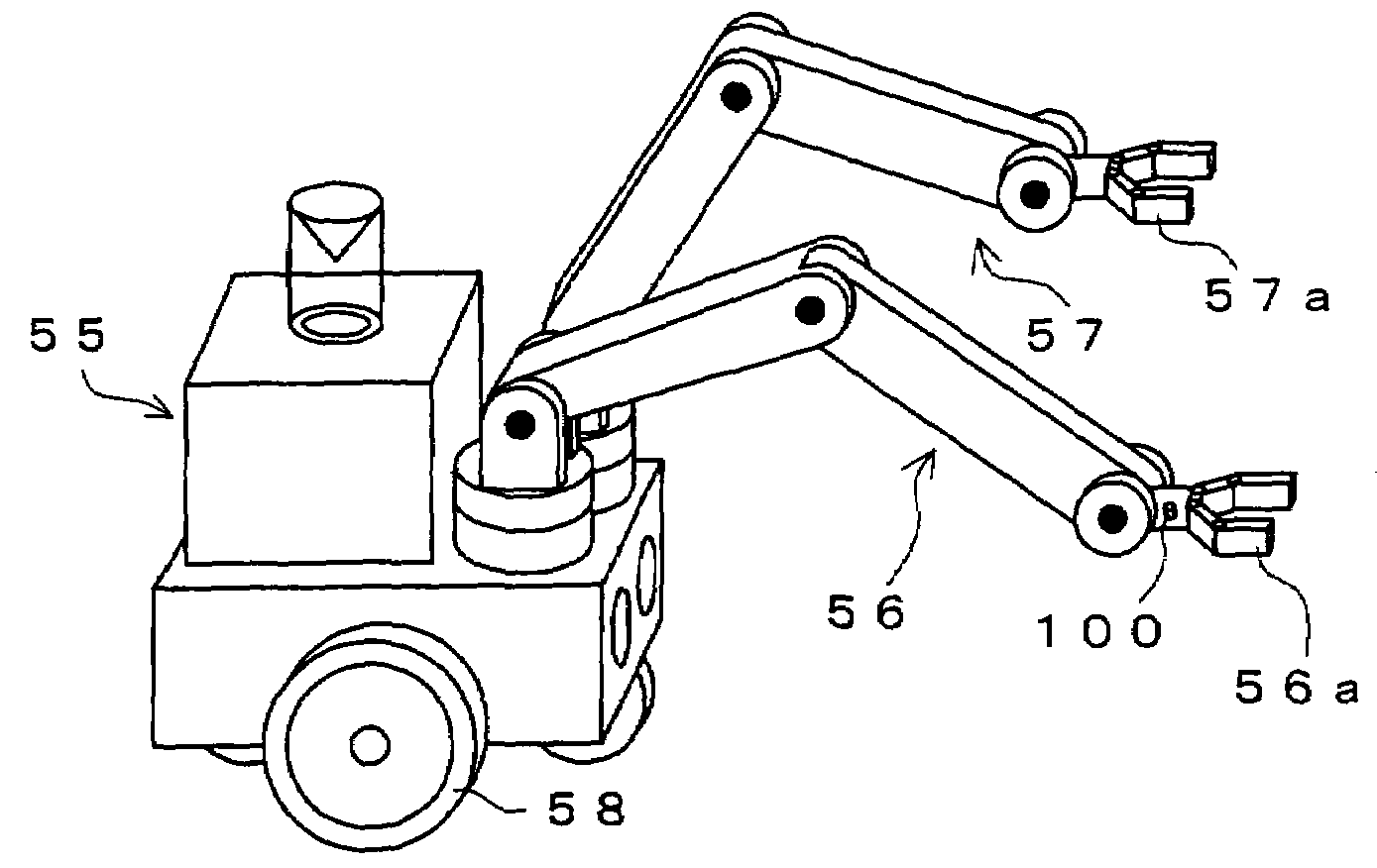
[0140]FIG. 8A is a view showing the construction of a robot controller 1A of the second embodiment of the present invention. As shown in FIG. 8A, the robot controller 1A of the second embodiment is constructed of first through fifth distributed control units 1a through 1e and constitutes function blocks by being arranged distributed in a body of an autonomous mobile robot 55 as a robot of one example of the object 3 to be controlled including left-hand and right-hand two arms 56 and 57 as shown in FIG. 8B. That is, the first distributed control unit 1a is an intelligence block that manages the planning and determination of motions, and the second and third distributed control units 1b and 1c are arm control blocks for controlling the motions of the two arms 56 and 57 that have end effectors 56a and 57a at the ends. The fourth distributed control unit 1d is a motion control block for managing the motions of the mobile robot 55 by driving left-hand and right-hand two wheels 58 and 58,...

third embodiment

[0182]FIG. 9A is a view showing the construction of a robot controller 1B of the third embodiment of the present invention. As shown in FIG. 9A, the robot controller 1B of the third embodiment has a structure separated into two sections of a movable-side control unit 11a provided for a mobile robot 18 as one example of the object 3 to be controlled and a fixed-side control unit 11b provided for a fixed member 18a. As shown in FIG. 9B, in the case of the application to the mobile robot 18, the sections that influence the real-time performance are integrated into the movable-side control unit 11a and mounted in the robot main body, and the other non-real-time sections are integrated into the fixed-side control unit 11b and fixedly placed in a fixed control unit 18a outside the robot main body of the mobile robot 18. By making wireless communications between the movable-side and fixed-side route selecting means 12a and 12b between antennas 20a and 20b, a mobile robot 18 that has high m...


PUM


Abstract

Realized is a robot controller capable of handling a large amount of data of images and so on necessary for advanced intelligence of control while securing a real-time performance with a simple structure. For this purpose, there are provided a motion control device for performing a calculation process for achieving motion control of an object to be controlled, a recognition and planning device for performing task and motion planning of the object to be controlled and recognition of outside world, an input / output interface for outputting a command to the object to be controlled and receiving as input, a state of the object to be controlled, and a route selecting device for controlling communications by switching connections among the motion control device the recognition and planning device, and the input / output interface. While controlling the communications by switching the connections among the motion control device, the recognition and planning device, and the input / output interface by the route selecting device, the motions of the robot of the object to be controlled are controlled on the basis of the results of the task and motion planning of the object to be controlled and the recognition of the outside world.

Description

TECHNICAL FIELD[0001]The present invention relates to a robot controller that has a decentralized hierarchical structure for a recognition and plan processing system for performing recognition, determination, task planning, motion planning, and so on and a motion control processing system for performing real-time control, for achieving an intelligent robot or the like. In this case, if a case of an assembling task is taken as an example, the task planning means a planning process at an abstract concept level as exemplified by a component assembling sequence or how to assemble components together. On the other hand, the motion planning means a planning process for desired trajectory generation for finger operation to achieve an actual assembling task and desired position generation for force control.BACKGROUND ART[0002]In order to achieve an intelligent robot that has advanced intellectual abilities, a recognition and plan processing system for performing intelligent processing of re...

Claims


Application Information

Patent Timeline
Patent Type & Authority Patents(United States)
IPC IPC(8): G06F19/00B25J9/10B25J9/16B25J13/00B25J13/08B25J19/00
CPCB25J9/1697G05B2219/40609G05B2219/39543
Inventor OKAZAKI, YASUNAOSAKIYAMA, KAZUYUKIASAI, KATSUHIKOYAMAMOTO, MASAKI
Owner PANASONIC CORP
Why Eureka
Try Eureka