Toolholder

a tool and tool technology, applied in the field of tool holders, can solve the problems of increasing the cost of machining operations

Inactive Publication Date: 2008-08-26
KENNAMETAL INC
View PDF17 Cites 15 Cited by
  • Summary
  • Abstract
  • Description
  • Claims
  • Application Information

AI Technical Summary

Problems solved by technology

As a result, a dedicated tool holder has been required for each desired unique lead angle, thereby increasing the costs associated with the machining operation.
Likewise, the clearance angles must be changed, in particular on the leading edge where the angle of the thread may exceed the typical clearance angles, resulting in interference.

Method used


Image

  • Toolholder
  • Toolholder
  • Toolholder

Examples


Embodiment Construction

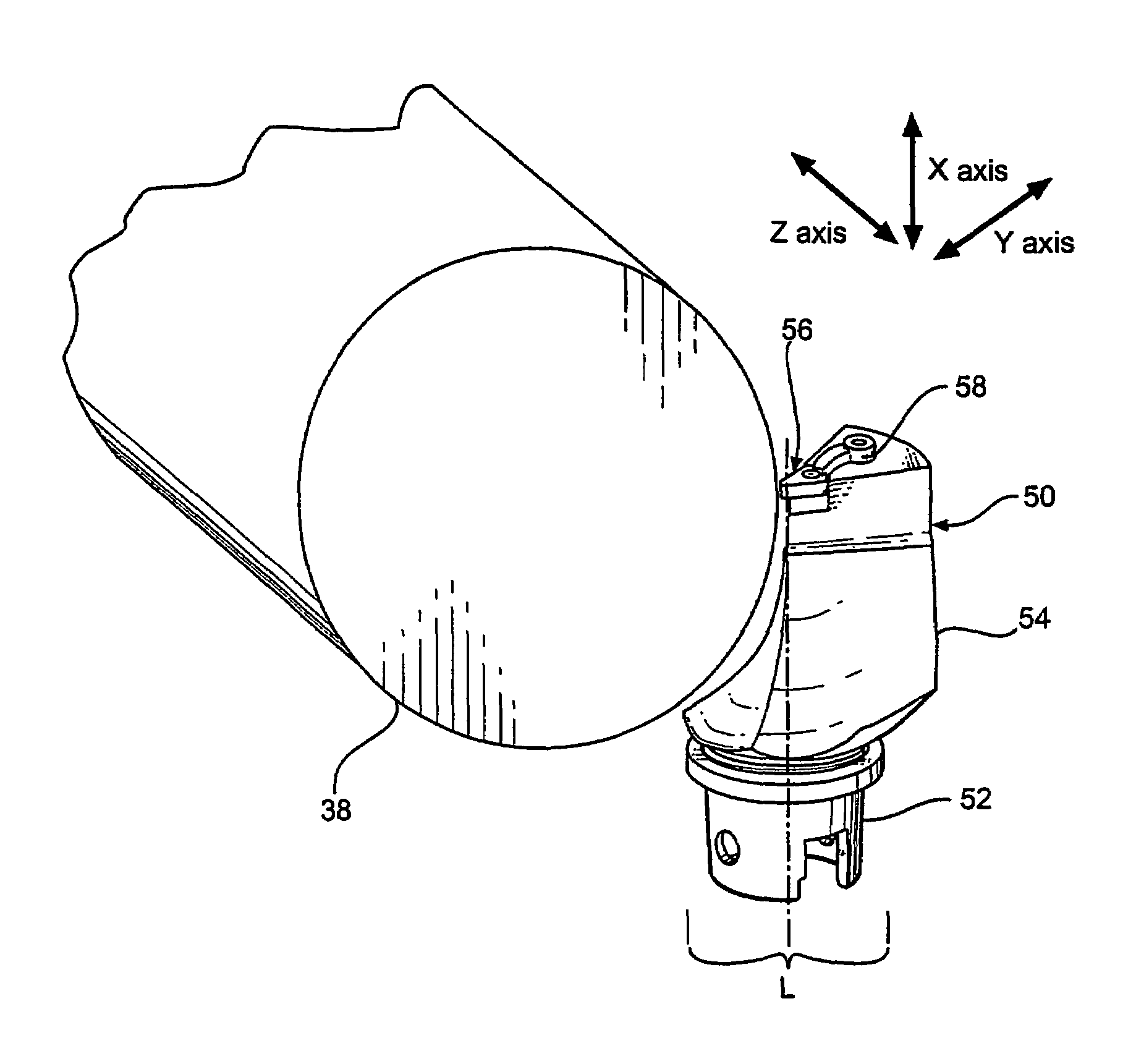
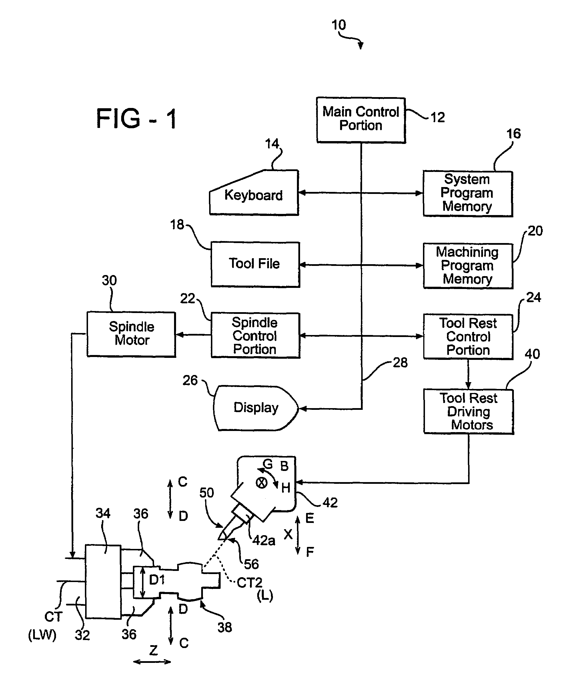
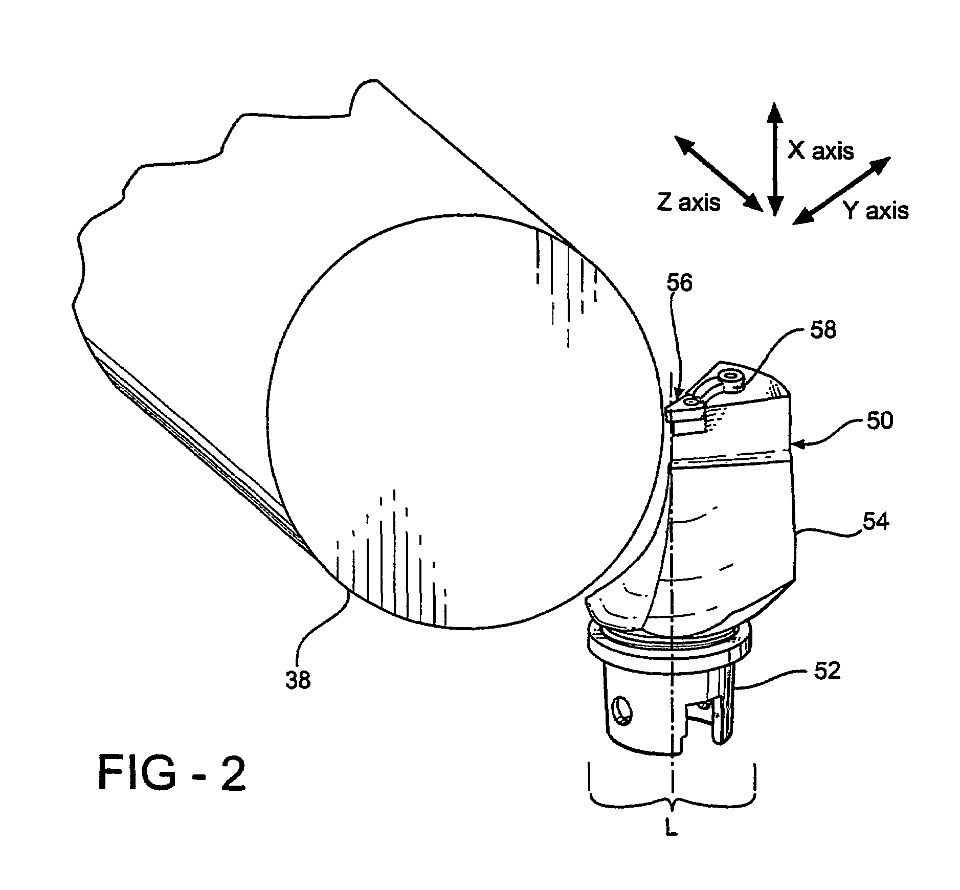
[0029]Referring to the drawings, wherein like reference characters represent like elements, FIG. 1 illustrates a machine tool 10 that is actuated by computer numerical controls (CNC). The machine tool 10 has a main control portion 12, an input portion 14, such as a keyboard, a system program memory 16, a tool file 18, a machining program memory 20, a spindle control portion 22, a tool rest control portion 24, and a display 26 that are connected through a bus line 28. A spindle motor 30 is connected with the spindle control portion 22. The spindle motor 30 rotates a spindle 32 with an axial center CT that is parallel to a direction of the Z-axis. The machine tool 10 also includes a chuck 34 with chuck jaws 36 for holding and releasing a work piece 38 having an outer diameter, D1. The spindle control portion 22 is capable of moving the work piece 38 in the X-axis direction, as indicated by arrows C and D. When the work piece 38 is installed in the chuck jaws 36, a longitudinal axis, L...


PUM

PropertyMeasurementUnit
lead angleaaaaaaaaaa
trailing angleaaaaaaaaaa
trailing angle constantaaaaaaaaaa

Abstract

A toolholder (50) with a controllable critical angle, such as a lead, trailing, rake or clearance angles, includes a tool spindle (42a) for retaining the toolholder in a tool rest (42) of a machine tool. The machine tool (10) includes at least one linear axis, for example, three mutually perpendicular axes, a rotary axis and a rotation axis. The rotary axis and / or rotation axis is controllable to move to a specified position in synchronization with a movement of one of the linear axes. An adaptor (54) supports a cutting tool (56) that is retained in the adaptor by a clamp (58). The cutting tool (56) defines a critical angle, such as a lead angle, a trailing angle, a rake angle and a flank clearance angle, wherein the critical angle is corrected as a vector of movement of at least one of the linear axis is changed. In addition, the cutting tool (56) can be positioned on opposite side of a centerline of rotation of the workpiece to effectively double the life of the cutting tool. A method of controlling a toolholder (50) is also disclosed.

Description

RELATED APPLICATION[0001]This application claims the benefit of U.S. Provisional Application No. 60 / 407,864, filed on Sep. 3, 2002.BACKGROUND OF THE INVENTION[0002]1. Field of the Invention[0003]This invention relates to a tool holder with selectable critical angles, such as a lead angle, a trailing angle, a rake angle, and a flank clearance angle. More particularly, this invention relates to machine tool for turning and threading operations, such as a lathe or a machining center, that allows a specified relationship between the insert geometry and the work piece to be selectively determined by a software program of a numerically controlled machine tool to maintain a critical angle between the insert and the work piece as the geometry of the work piece changes.[0004]2. Description of the Related Art[0005]In most advanced machine tools, movement and control of the machine and its components are actuated by computer numerical controls (CNC). These machine tools are usually equipped wi...

Claims


Application Information

Patent Timeline
Patent Type & Authority Patents(United States)
IPC IPC(8): B23C5/10B23D1/00B23D1/20B23D13/00B23B1/00B23Q15/00B23B21/00B23B25/06B23B29/04
CPCB23B1/00B23B29/04B23B29/046B23B27/14Y10T409/309464G05B2219/50297G05B2219/50353Y10T409/50Y10T407/21Y10T409/303808Y10T29/49316Y10T82/2502Y10T409/501476Y10T407/1948Y10T82/2587
Inventor HYATT, GREGORY A.MASSA, TED R.ANDRAS, LINN R.STOHR, JAMES J.
Owner KENNAMETAL INC
Why Eureka
Try Eureka