Intravascular material removal device

a technology of material removal and intravascular wall, which is applied in the field of intravascular material removal device, can solve the problems of reducing the delivery profile, occlusion, further blockage, etc., and achieves the effect of low delivery profil

Inactive Publication Date: 2008-08-26
MEDTRONIC VASCULAR INC
View PDF12 Cites 29 Cited by
  • Summary
  • Abstract
  • Description
  • Claims
  • Application Information

AI Technical Summary

Benefits of technology

[0012]An embodiment according to the present invention provides an intravascular material removal device that removes material from a vessel wall and creates flow dynamics that draw the material into a catheter device for removal from the vessel. A collapsible device provides a relatively low delivery profile while being expandable in use to adapt to varying and variable vessel diameters.
[0014]The device has a material removing element that may be selected from a plurality of material removing elements having different properties, e.g., stiffness, flexibility, bristles of various sizes, etc for removing different types of material from gelatinous deposits like thrombus to harder deposits such as calcium deposits.
[0017]In one variation of the embodiment, the bristles are retractable so that the delivery profile of the device may be reduced for delivery through the vasculature. The device in one variation provides bristles that may flex when retracted into a catheter. Another embodiment provides an inner elongate member with a plurality of bristles formed in a spiral-like configuration attached to the inner member and an outer member positioned over the elongate member having at least one opening through which the bristles may extend. The outer member and inner member are configured to move axially with respect to each other so that the outer member engages to retract the bristles to provide a smaller radius device or alternatively permit the bristles to extend through the opening to a produce a larger radius device.

Problems solved by technology

Plaque, fat deposits, calcium deposits, thrombus, blood clots, etc. deposited on the inner walls of the blood vessel may cause narrowing or occlusion of the blood vessels, cutting off or restricting blood flow and / or presenting a dangerous condition in which the material may break off and travel through the vasculature causing further blockages, clots or embolisms.
This method, however, does not provide a means for removing the material deposited on the vessel wall.
Laser techniques currently used carry with them the risk of overheating tissue and burning holes in the vessel walls.
The openings formed in the blockages are also limited by the size of the laser.
These devices have been problematic where the cut material moves downstream forming another blockage or clot.
Such devices also have not worked particularly well on thrombus or clots.
Also, the large cutting head size relative to the delivery path, that is required to effectively remove material from the vessel wall, makes the cutting device difficult to deliver.
However, these devices require actuation to expand or contract the cutting heads and they do not adapt sufficiently to change in circumference of the vessel along its length or as the device is advanced through the vessel while cutting.
This technique includes a risk of perforation and damage to vessel from the high pressure jetted fluid.
It is also a slow process that takes significant physician and patient table time to perform.
These devices are relatively complex requiring placement of a balloon on each side of the blockage.

Method used


Image

  • Intravascular material removal device
  • Intravascular material removal device
  • Intravascular material removal device

Examples


Embodiment Construction

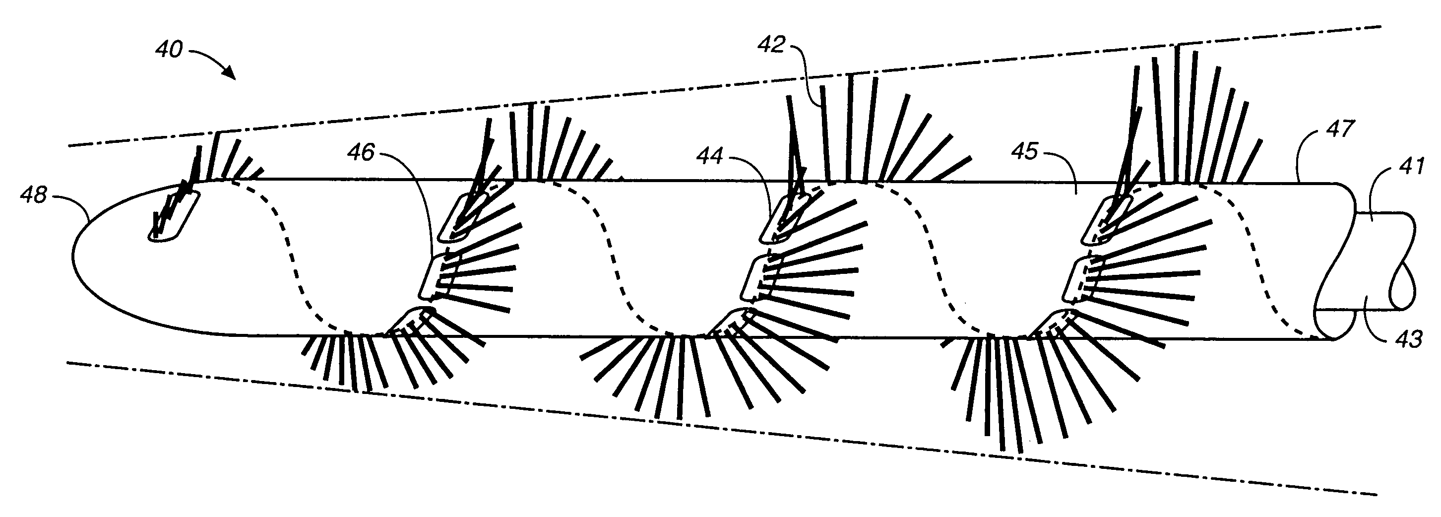
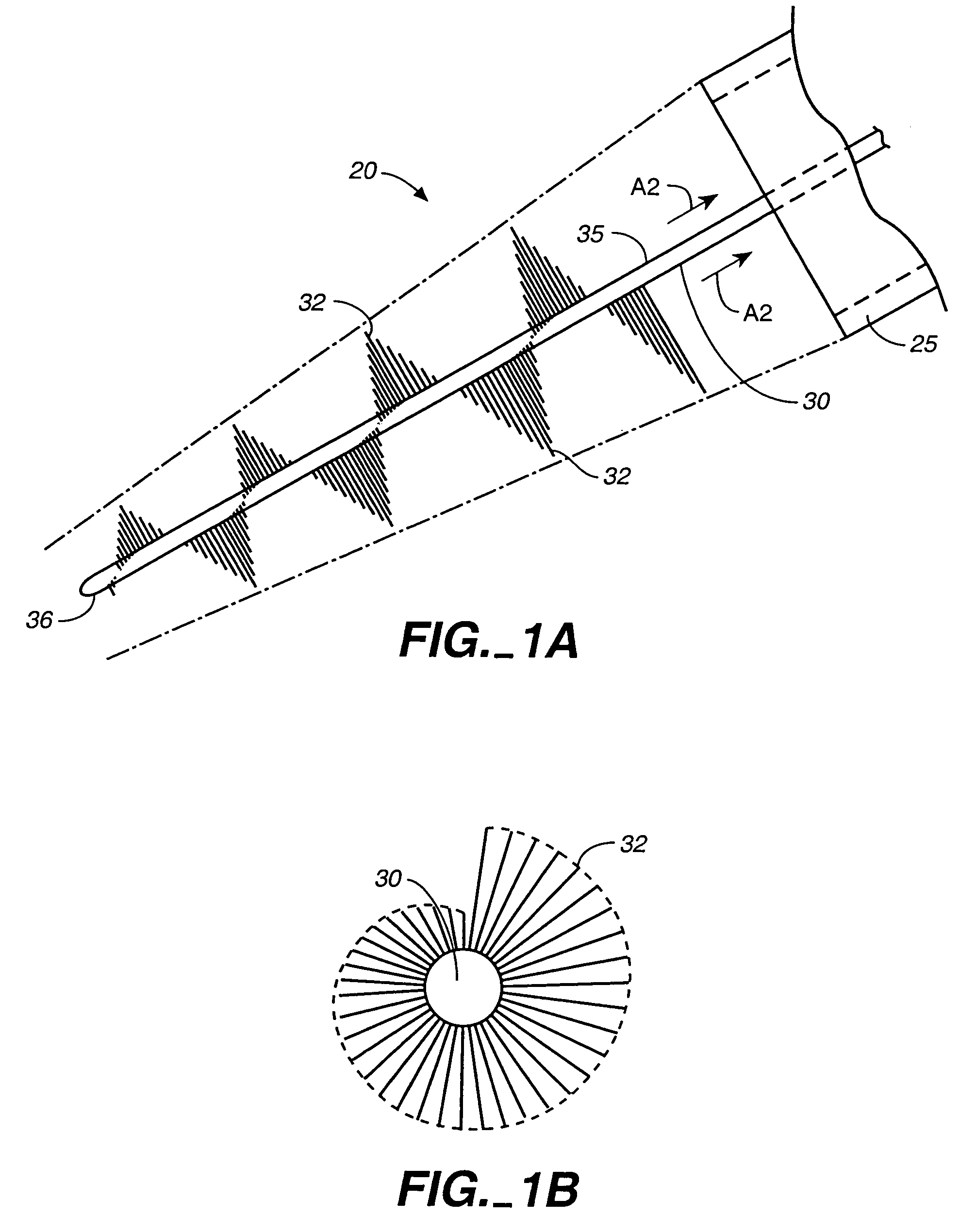
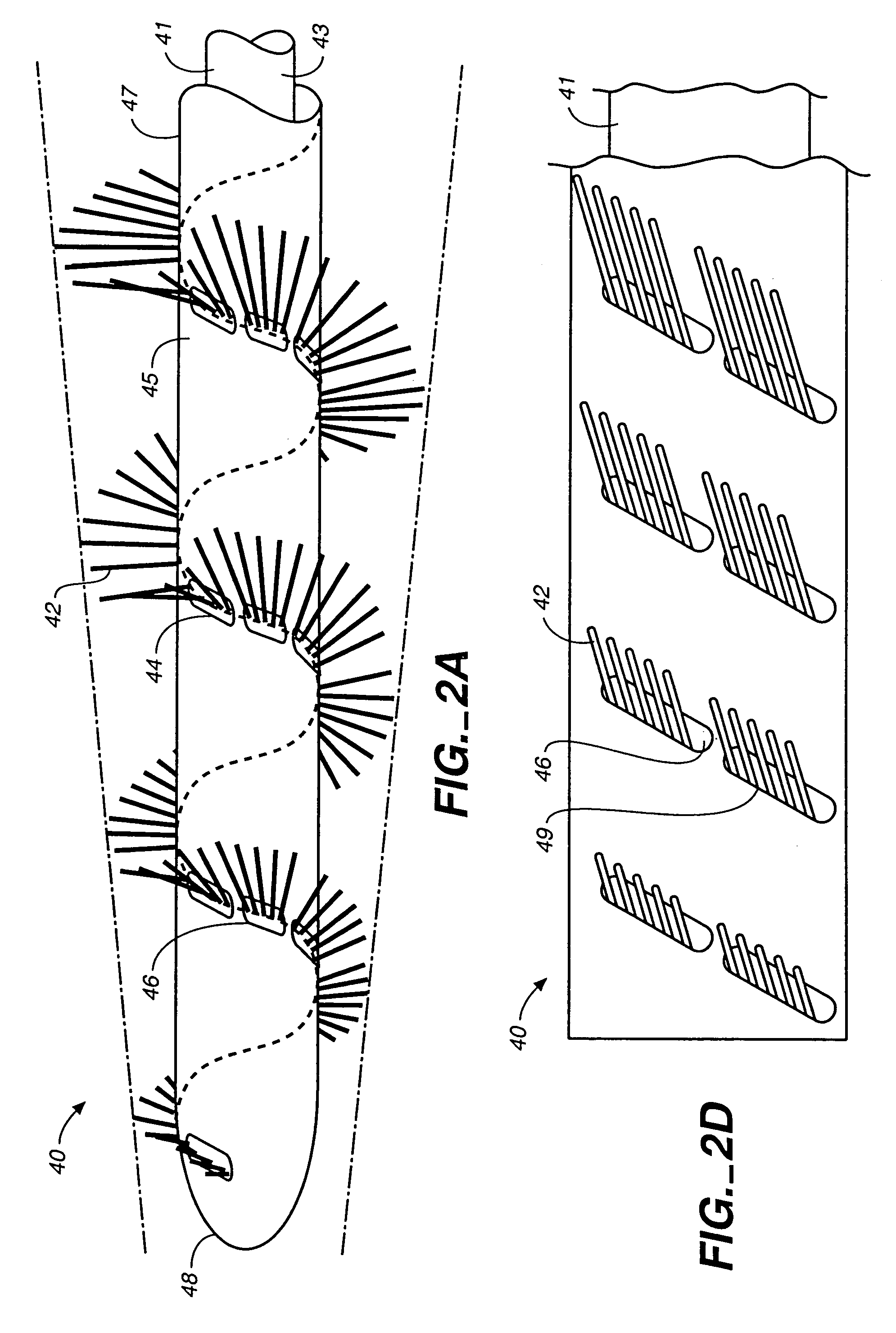
[0029]Referring to FIGS. 1A and 1B, an intravascular material removing device 20 is illustrated including a delivery catheter 25 and an elongate member 30 with a plurality of bristles 32 formed in a spiral arrangement along the length of the elongate member 30. The elongate member 30 is illustrated in a position extending out of a delivery catheter 25. The limits of the arc circumscribed by the bristles 32 gradually taper from a proximal portion 35 to a distal end portion 36 of the elongate member 30. When the elongate member 30 is retracted into the delivery catheter 25, the bristles 32 may flex or bend so that they fit within the delivery catheter 25. Thus the elongate member 30 is retractable into a catheter having a smaller diameter than the outer diameter of the elongate member when the bristles are not constrained.

[0030]As illustrated in FIG. 3, in use, the elongate member is delivered percutaneously through the catheter 25 to a blocked portion 71 of a vessel 70. In this parti...


PUM


Abstract

An intravascular material removal device that removes material from a vessel wall and creates flow dynamics that draw the material into a catheter device for removal from the vessel is provided. A collapsible device that provides a relatively low delivery profile while being expandable in use to adapt to varying and variable vessel diameters is also provided. A spiral configured material removing element is provided that can adapt to varying vessel diameters and to remove material forming blockages or occlusions from the inner wall of a vessel.

Description

RELATED APPLICATIONS[0001]This application is a divisional of U.S. application Ser. No. 10 / 423,266 filed Apr. 25, 2003, the entire contents of which are hereby incorporated by reference.FIELD OF THE INVENTION[0002]The invention relates to a device for removing material such as thrombus, plaque, and clots, from a body lumen such as a blood vessel.BACKGROUND OF THE INVENTION[0003]Plaque, fat deposits, calcium deposits, thrombus, blood clots, etc. deposited on the inner walls of the blood vessel may cause narrowing or occlusion of the blood vessels, cutting off or restricting blood flow and / or presenting a dangerous condition in which the material may break off and travel through the vasculature causing further blockages, clots or embolisms.[0004]A variety of devices have been proposed for forming a channel in or removing such material from a vessel.[0005]Guidewires have been used to channel through such deposits and a balloon passed over the guidewire is then used to form an opening. ...

Claims


Application Information

Patent Timeline
Patent Type & Authority Patents(United States)
IPC IPC(8): A61B17/22A61B17/32
CPCA61B17/320725A61B17/320758A61B2017/320733A61B2017/320012
Inventor KRIVORUCHKO, MICHAEL
Owner MEDTRONIC VASCULAR INC
Why Eureka
Try Eureka