Wind power generation system, arrangement of permanent magnets, and electrical power-mechanical force converter

a technology of wind power generation and permanent magnets, applied in the direction of electric generator control, renewable energy generation, greenhouse gas reduction, etc., can solve the problems of inability to generate electric power once stopped, no power generator has come into practical use that can respond, etc., to save energy used for cooling or heating, improve power generation efficiency, and efficiently generated

Inactive Publication Date: 2008-08-26
SHIRO KINPARA
View PDF37 Cites 82 Cited by
  • Summary
  • Abstract
  • Description
  • Claims
  • Application Information

AI Technical Summary

Benefits of technology

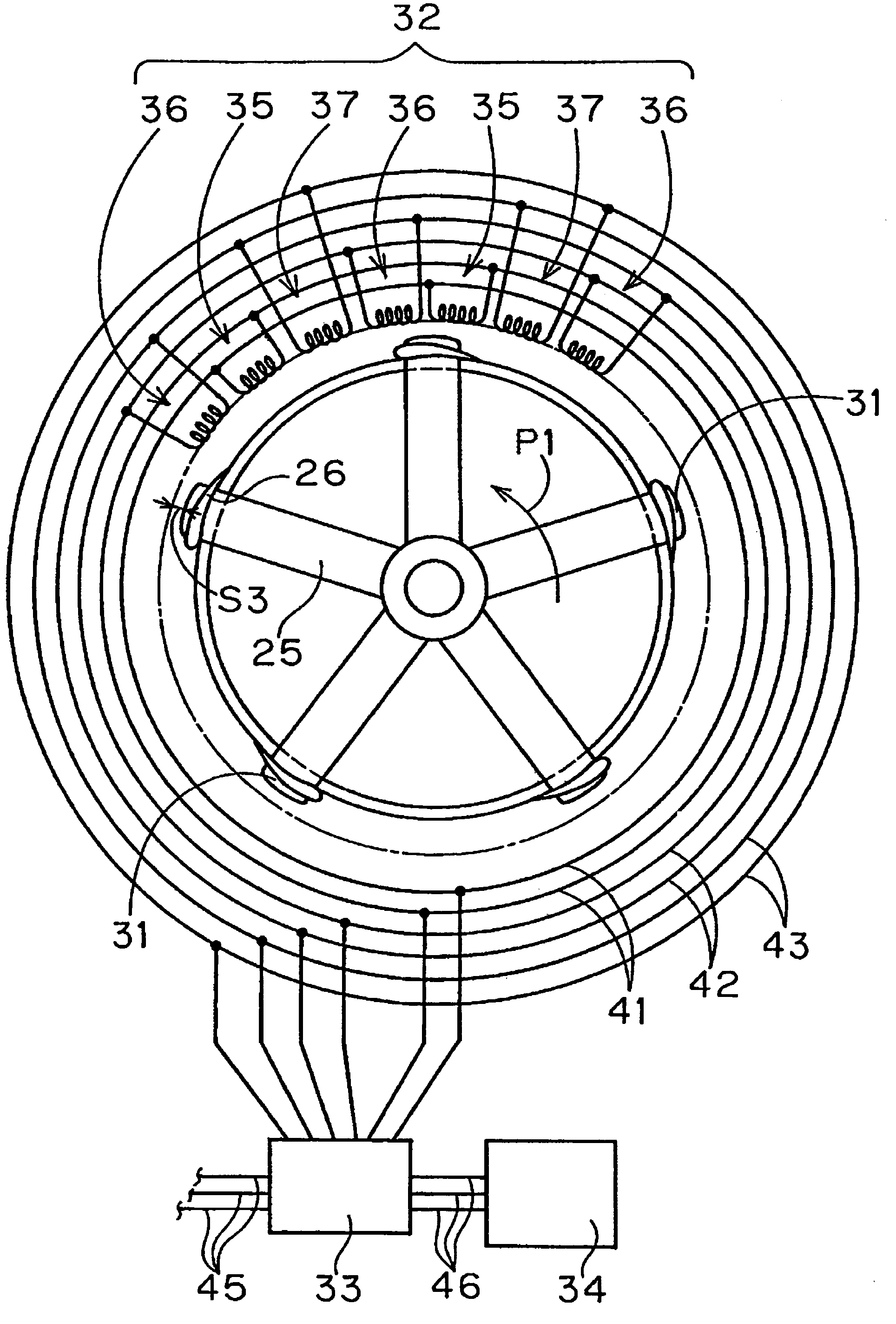
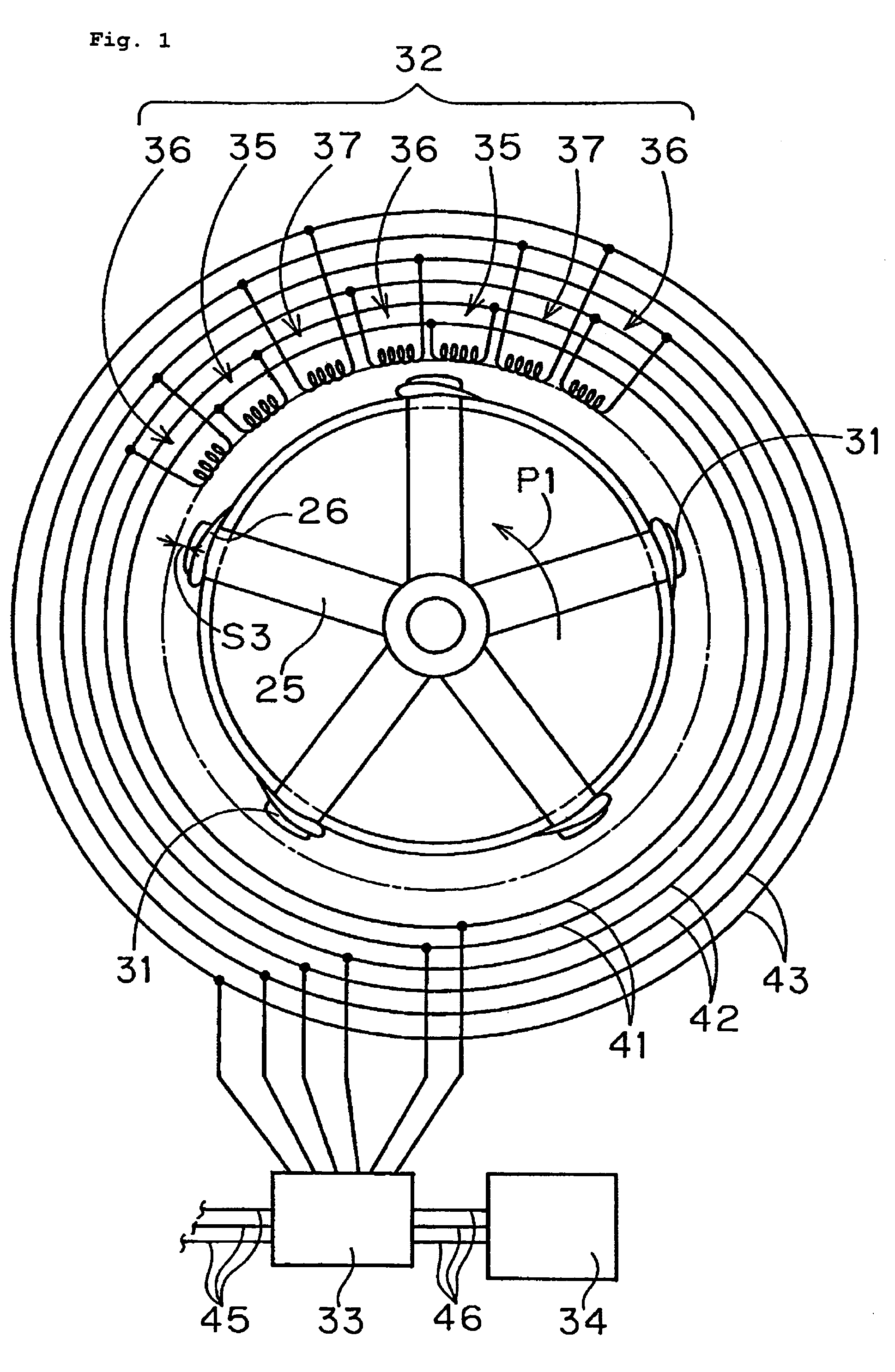
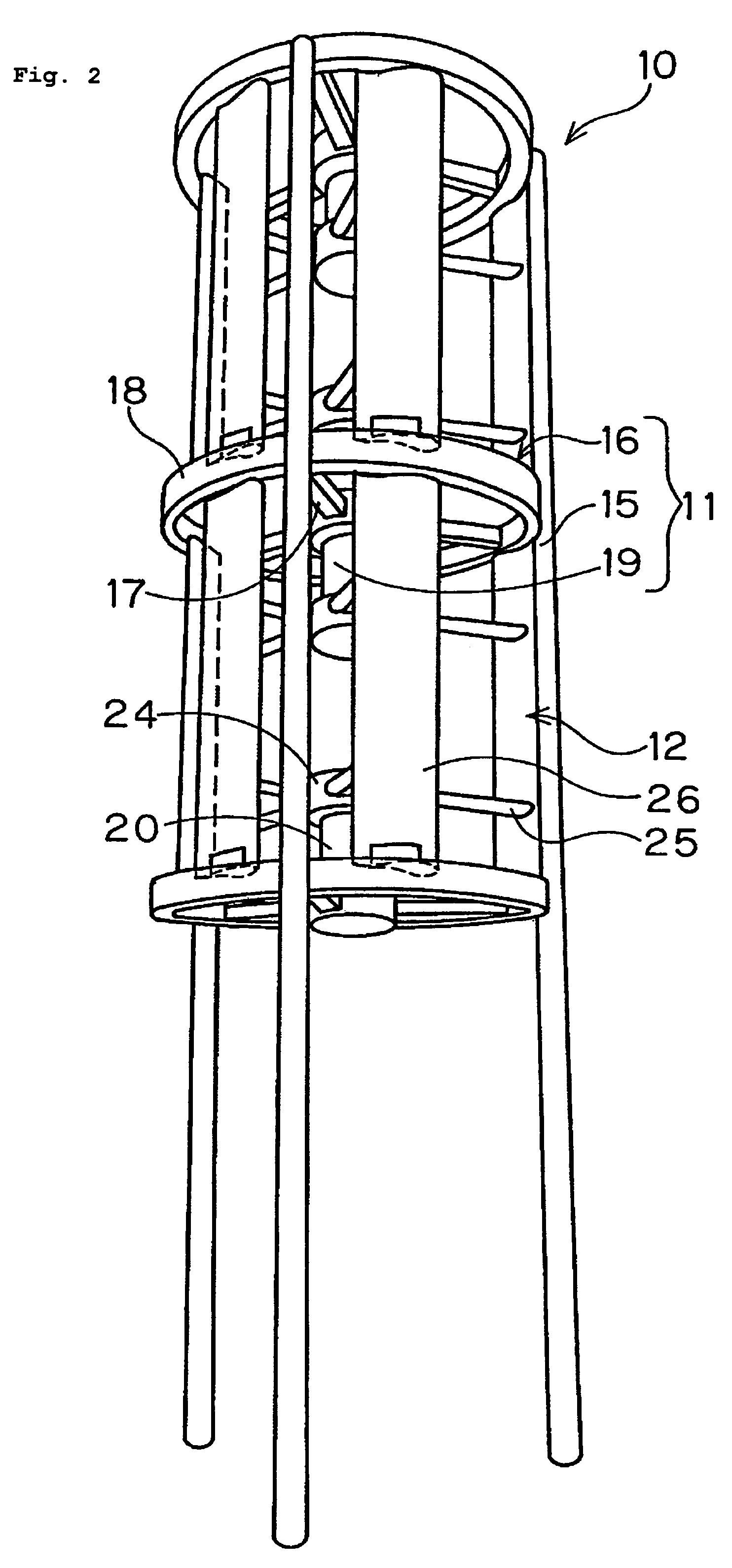
[0032]In this wind power generation system of the present invention, when the impeller rotates the field magnet and the coil provided on the frame and the impeller respectively generates an electric power by the inverse action of a linear motor. A large number of such field magnet and coil can be aligned along the periphery or mid periphery of the impeller quickening the relative speed. Further, since the electric power is generated at the periphery of the impeller, it is not necessary to transmit large power to the central part saving the weight of the impeller. Therefore, the impeller is easily rotated by a slight (weak) wind, and even the slow rotation of the impeller can generate sufficient amount of electric power by the coils.
[0059]The heat exchange system of this invention can retrieve the heat of the heat medium which is cooled or heated by the second heat exchanger using the first heat exchanger located near the ground saving the energy used for cooling or heating. Further, utilizing the above wind power generation system for the circulation of the heat medium, more saving of the energy can be attempted.

Problems solved by technology

However, no power generator has come into practical use that can respond to the wide variation from weak winds to strong winds.
However, in a weak wind condition, it once stops due to the insufficient torque.
Therefore, it cannot generate an electric power until a strong wind overcoming static friction resistances blows.
Further, since it requires the transmission of torque from the peripheral longitudinal blades to the center shaft by the supporting shaft etc. the weight of the impeller becomes larger causing the rotation under a weak wind more difficult.
Therefore, in case of typhoon etc. there is a possible damage of the impellers.

Method used


Image

  • Wind power generation system, arrangement of permanent magnets, and electrical power-mechanical force converter
  • Wind power generation system, arrangement of permanent magnets, and electrical power-mechanical force converter
  • Wind power generation system, arrangement of permanent magnets, and electrical power-mechanical force converter

Examples


first embodiment

[0192]Next, referencing FIG. 28˜36, the electric power-mechanical force converter of this invention is described. FIG. 28 shows a block drawing (cross section) of the power generator having magnetic poles in the both sides as shown in FIG. 21 in the previous embodiment of the wind power generation system. The mechanical power-electric power converter comprises a rotor 127 having permanent magnets 126 in the both sides, bearings 128 supporting the shaft of the rotor 127, a pedestal 129 to support the bearing 129, the driving part 130 composed of the impeller 12 to rotate the rotor 127, and the stator 131 facing the permanent magnets 126 of the rotor 127. In place of the bearing 128, the above described magnetic levitation by permanent magnets may be used. The mechanical power-electric power converter extends perpendicular to the paper. When it is applied to a wind power generator, it is aligned annularly, but it may be aligned in straight line or in gradual curve. The following descr...

third embodiment

[0234]Next, referencing FIG. 45˜51, the electric power-mechanical force converter of this invention is described. FIG. 45 shows a block diagram of the power generator as shown in FIG. 21 having the rotor that has the poles in both sides in the previous embodiment of the wind power generation system. The power generator comprises the rotor 164 having the permanent magnets 163 in the both sides, the bearing part 165 which supports the rotor 164 at its shaft, the pedestal 166 to support the bearing part 165, the prime mover 167 composed of the impeller 12 etc. which rotates the rotor 164, the stators 170 facing the permanent magnet 163 of the rotor 164. In place of the above bearing part 165, the above described magnetic levitation structure may be employed.

[0235]In the power generator having the stator 170 in the both sides of the rotor 164, even if the outer and the inner stator coil is aligned geometrically, the magnetic flux distribution of the outer stator 170a and the inner stato...


PUM


Abstract

A wind power generation system 10 comprising a frame, an impeller 12 rotatably supported by the frame, plural permanent magnets 31 aligned at equal intervals from the rotation center, and coils 32 aligned annularly on the frame. The relative motion of the permanent magnets 31 and the coils 32 in close vicinity generates electric powers by the inverse action of a linear motor. The coils 32 are mounted on the ring provided on the frame, and the permanent magnets 31 are provided on the lower end of the longitudinal blades 26 of the impeller.

Description

FIELD OF THE INVENTION[0001]This invention relates to a wind power generation system, alignments of permanent magnets, and an electrical power-mechanical force converter, and more particularly to a power generating system employing a power generator based on the principle of linear motor, alignments of permanent magnets and an electrical power-mechanical force converter to be preferably employed in a wind power generation system.[0002]The concept of “an electrical power-mechanical force converter” described herein includes both an apparatus provided with a function of generating electric powers by converting a mechanical energy to an electrical energy and an apparatus provided with a function of motor converting an electrical energy to a mechanical energy, and further includes an apparatus exerting both functions by operation.BACKGROUND ARTS[0003]In the Japanese Patent Publication No.H3-10037 (hereinafter referred to as Patent Publication 1), a wind power generator is disclosed, whe...

Claims


Application Information

Patent Timeline
Patent Type & Authority Patents(United States)
IPC IPC(8): F03D11/00F03D3/02H02K7/18
CPCF03D3/02F03D9/002F03D9/021H02K7/14H02K7/183Y02E10/74F05B2220/7068F03D9/007F03D9/11F03D9/25F03D13/20Y02E10/72Y02E10/728Y02E70/30Y02P90/50F03D1/04F03D3/04F03D9/00H02K21/12
Inventor UCHIYAMA, HISAKAZU
Owner SHIRO KINPARA
Why Eureka
Try Eureka