Image processing system, server, image processing apparatus, management method, computer program, and storage medium

Inactive Publication Date: 2008-08-26
MINOLTA CO LTD
View PDF39 Cites 9 Cited by
  • Summary
  • Abstract
  • Description
  • Claims
  • Application Information

AI Technical Summary

Benefits of technology

[0022]This structure of the invention makes it is possible to select the apparatus having the shortest elapsed time since the image quality stabilization processing was last executed (i.e. the apparatus capable of executing image processing of the highest image quality), and thus reduce the inconvenience to the user of low image quality print output resulting from the user selecting the external ap

Problems solved by technology

Variations in internal temperature and wear and tear on the photosensitive drum and other structural elements, for example, result in the image density and image positioning relating to an executed jobs failing to meet target control values, and the quality level of processed images (hereafter “image quality level”) suffers as a result.
However, one of the disadvantages of frequent execution of the stabilization processing is the fact that jobs cannot be processed while the stabilization processing is being executed.
Inconvenience results for the user in terms of waiting time.
However, the fact is that users of such a system are not guaranteed a high image quality of print output despite the inclusion in the system of image formin

Method used


Image

  • Image processing system, server, image processing apparatus, management method, computer program, and storage medium
  • Image processing system, server, image processing apparatus, management method, computer program, and storage medium
  • Image processing system, server, image processing apparatus, management method, computer program, and storage medium

Examples


Example

First Embodiment

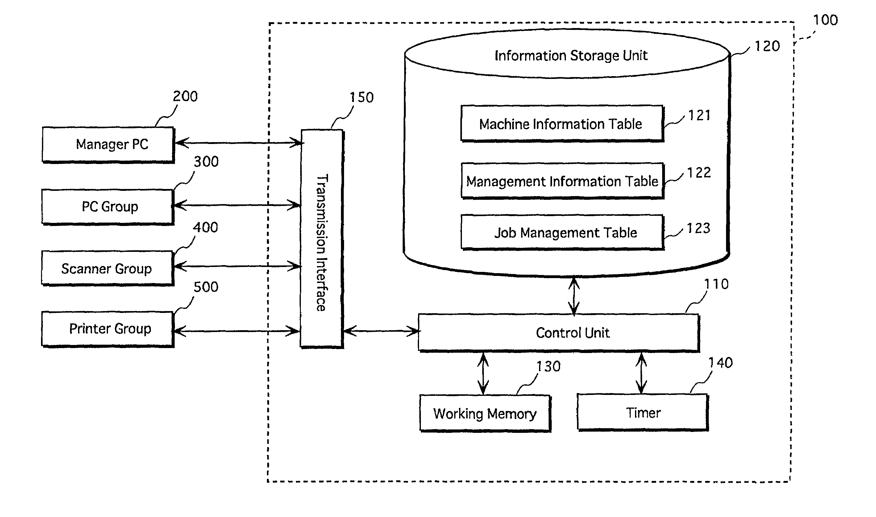
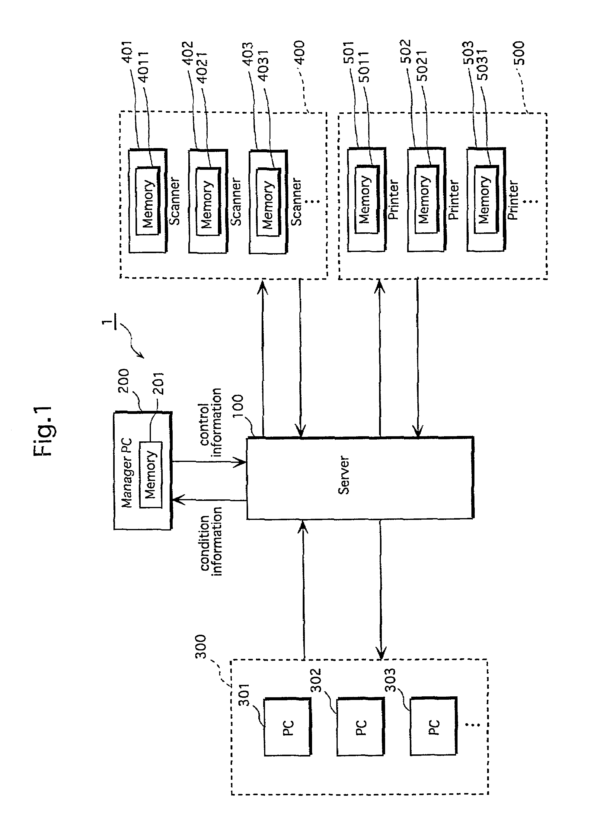
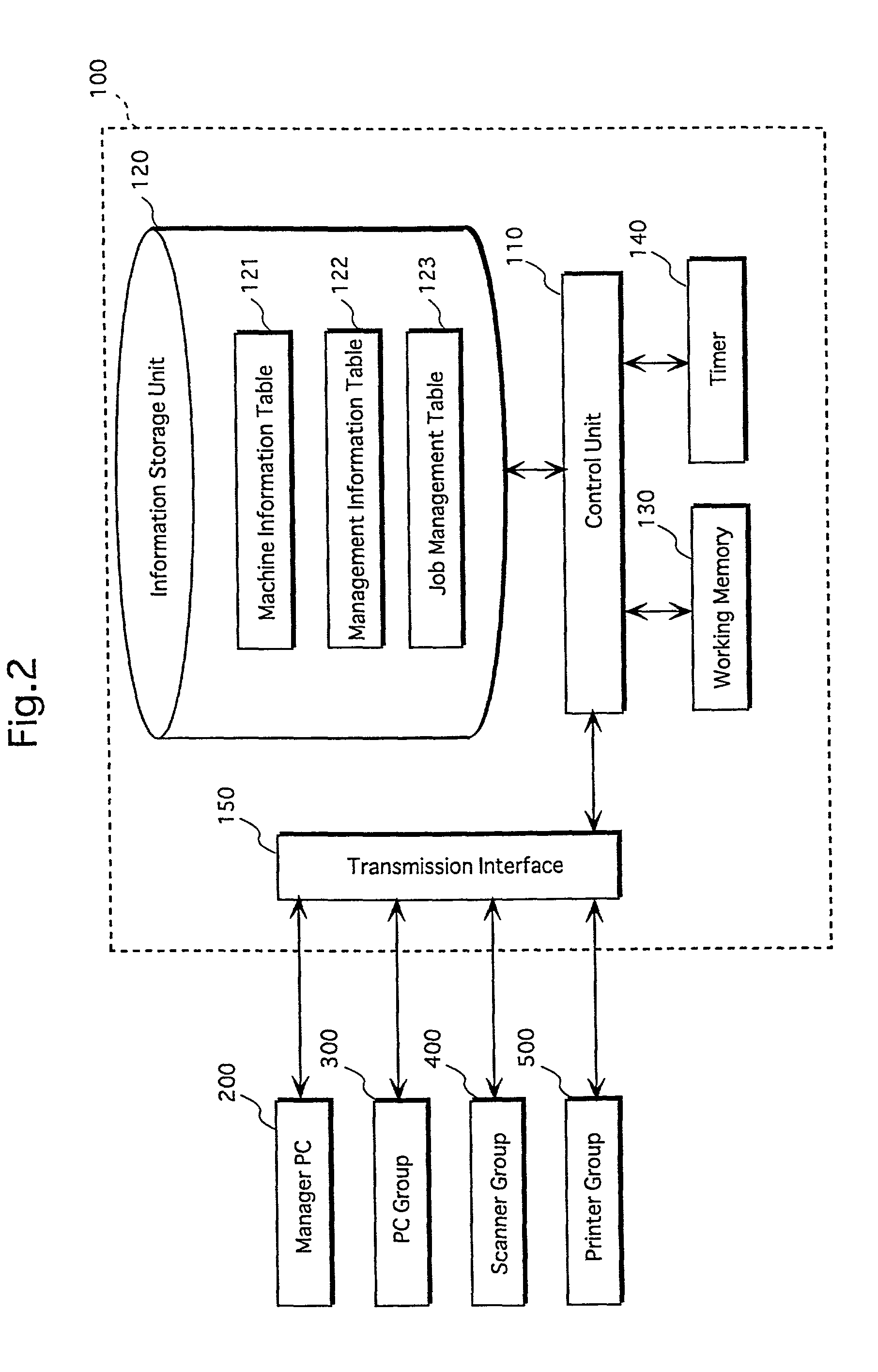
[0057]FIG. 1 shows an exemplary structure of image processing system 1 (hereafter “system 1”) according to a first embodiment of the present invention.

[0058]System 1 includes a server 100, personal computers 301, 302, 303, . . . (PC group 300), scanners 401, 402, 403, . . . (scanner group 400), printers 501, 502, 503, . . . (printer group 500), and a personal computer 200 (hereafter “manager PC 200”) operated by a manager in order to manage system 1. The elements of system 1 are connected to each other via a LAN or similar network.

[0059]Manager PC 200 and the PCs comprising PC group 300, in addition to having a computer body that includes a hard disk (HD), a monitor connected to the body, and a keyboard, each include a network compatible operating system (OS) preinstalled in the HD, a print driver, and application software for conducting wordprocessing and the like.

[0060]When one of the PCs in PC group 300 requests print processing of a document created using the app...

Example

Second Embodiment

[0222]Whereas the first embodiment was structured such that server 100 managed the execution interval of the stabilization processing in an external apparatus using time as a basis, in the second embodiment, time is replaced by the number of image processing operations as the basis to determine the timing of the stabilization execution. In a printer the number of image forming operations is used as a basis, and in a scanner the number of image reading operations is used as a basis.

[0223]With increases in the number of image processing operations executed in an external apparatus, there occurs a reduction in the image quality of print output as a result of the deterioration of the photosensitive drum and other elements. Thus the same effects as the first embodiment can be achieved by calculating the execution interval of the stabilization processing operation using the number of image processing operations executed by an external apparatus. In this case, the external...


PUM


Abstract

In an image processing system in which a server, a plurality of image processing apparatuses that execute image quality stabilization processing, and a terminal apparatus are connected to each other via a network, the server calculates, with respect to each image processing apparatus, the time period elapsed since the image quality stabilization processing was last executed, and selects the apparatus having the shortest elapsed time period as the apparatus to execute a job requested by the terminal apparatus.

Description

[0001]This application is based on application no. 2001-102626 filed in Japan, the content of which is hereby incorporated by reference.BACKGROUND OF THE INVENTION[0002]1. Field of the Invention[0003]The present invention relates to an image processing system, a server, an image processing apparatus, a management method, a computer program, and a storage medium, the system including the server, a plurality of image processing apparatuses, and a terminal apparatus, which are connected to each other via a network.[0004]2. Related Art[0005]In printers and other known image processing apparatuses a reduction in image quality levels occurs when jobs are executed continuously under fixed control conditions. Variations in internal temperature and wear and tear on the photosensitive drum and other structural elements, for example, result in the image density and image positioning relating to an executed jobs failing to meet target control values, and the quality level of processed images (h...

Claims


Application Information

Patent Timeline
IPC IPC(8): G06F3/12G01D18/00G06K15/02H04N1/00B41J29/38B41J29/46G03G21/00H04N1/32
CPCH04N1/00013H04N1/00042H04N1/0005H04N1/00061H04N1/00888H04N1/00954H04N1/32502H04N1/32507H04N1/32523H04N1/32539H04N1/00015H04N2201/0082H04N1/00127H04N1/00204H04N1/00344H04N1/00885H04N2201/0081
Inventor IMAIZUMI, SHOJIKAWABUCHI, YOICHIIKENOUE, YOSHIKAZU
Owner MINOLTA CO LTD
Why Eureka
Try Eureka