
Fluid jet drilling tool

a technology of fluid jet and drilling tool, which is applied in the direction of drilling pipes, drilling holes/well accessories, cutting machines, etc., can solve the problems of unsatisfactory erosion, less effective use of fluid jet and energy contained

Inactive Publication Date: 2008-09-02
SHELL OIL CO
View PDF94 Cites 6 Cited by
  • Summary
  • Abstract
  • Description
  • Claims
  • Application Information

AI Technical Summary

Benefits of technology

The invention provides a distance holder for an excavating device that generates a stream of abrasive fluid to create holes in geological formations. The holder has a trumpet-shaped inner surface with an opening that allows the fluid to pass through and impact the formation. The device also includes a rotating body and a nozzle to jet the fluid onto the surface. The distance holder ensures a consistent distance between the nozzle and the surface, resulting in more accurate and efficient excavation.

Problems solved by technology

This may lead to misalignment of the abrasive jet stream, and thereby undesired erosion into the bore hole wall, and a less effective use of the abrasive jet and the energy contained therein.

Method used


Image

  • Fluid jet drilling tool
  • Fluid jet drilling tool
  • Fluid jet drilling tool

Examples


Embodiment Construction

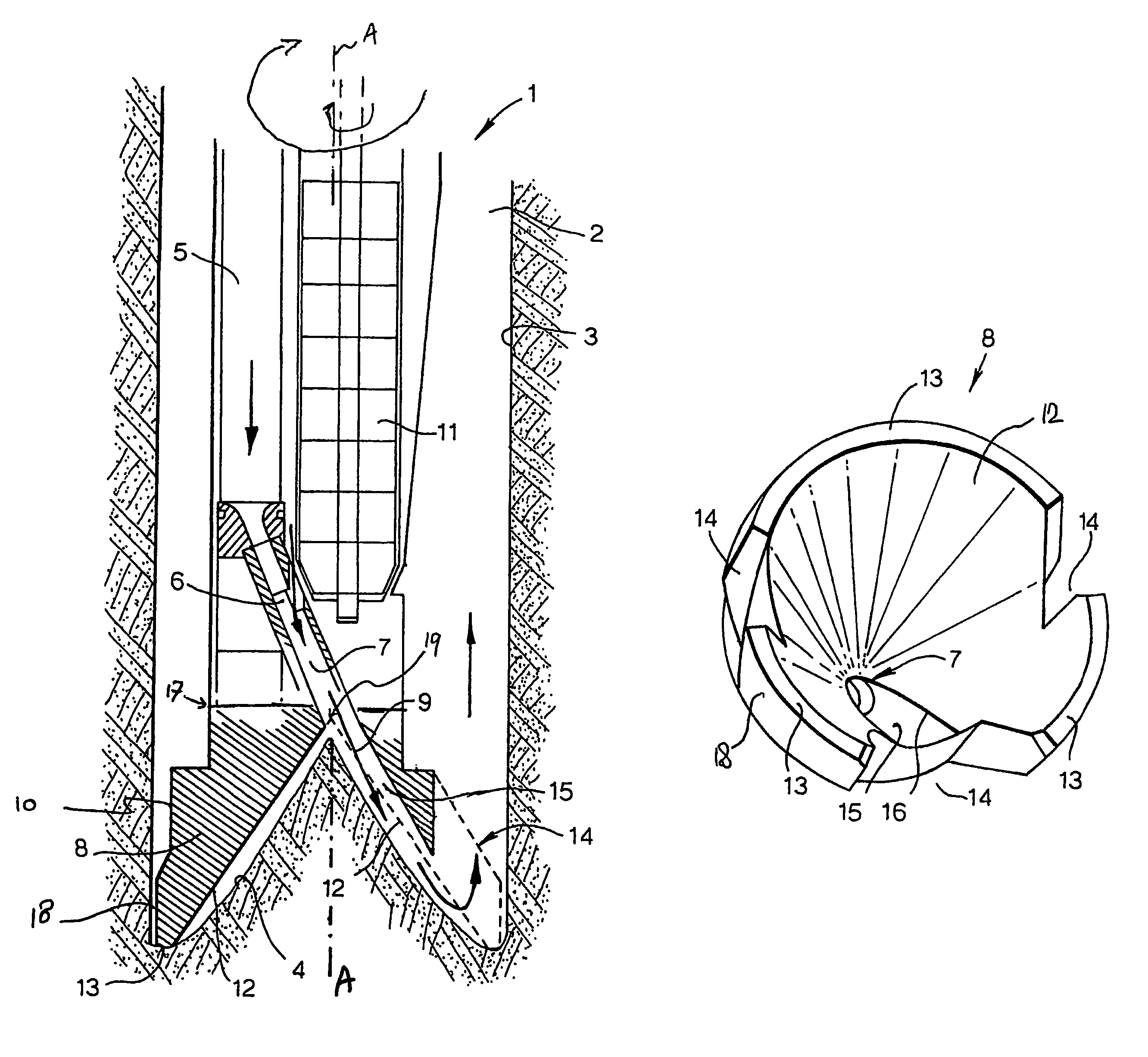
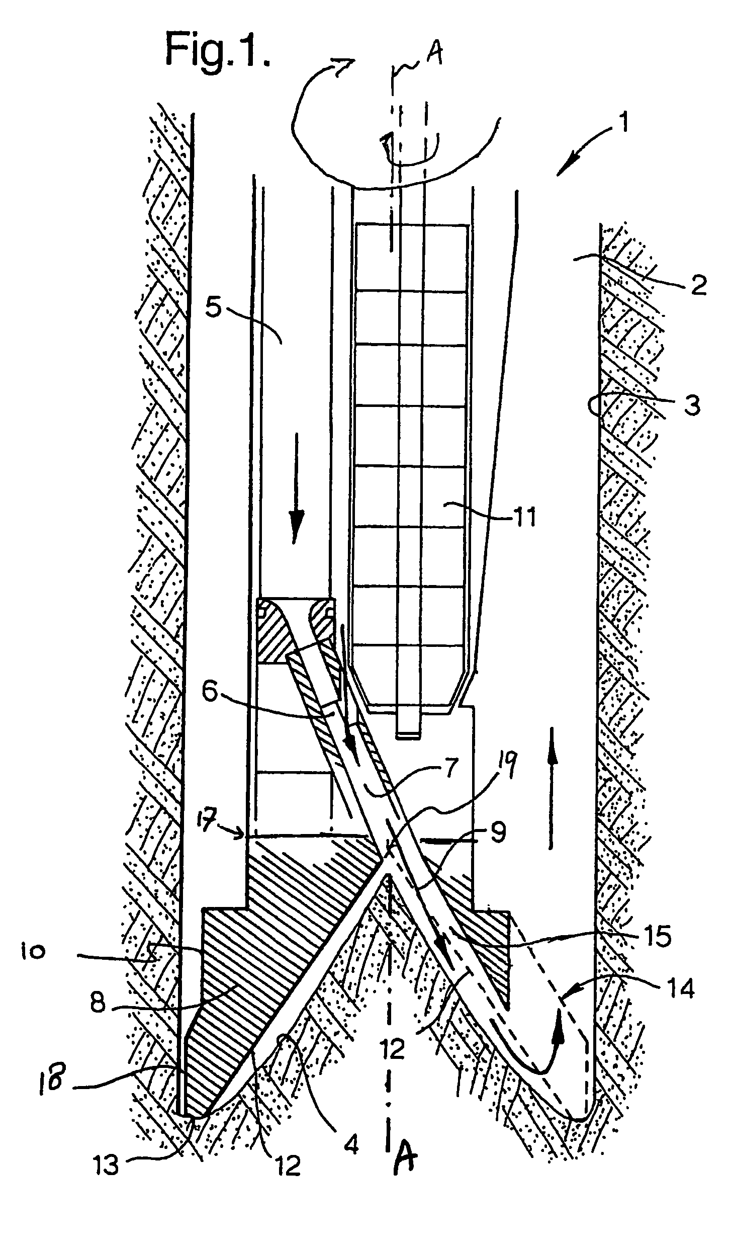
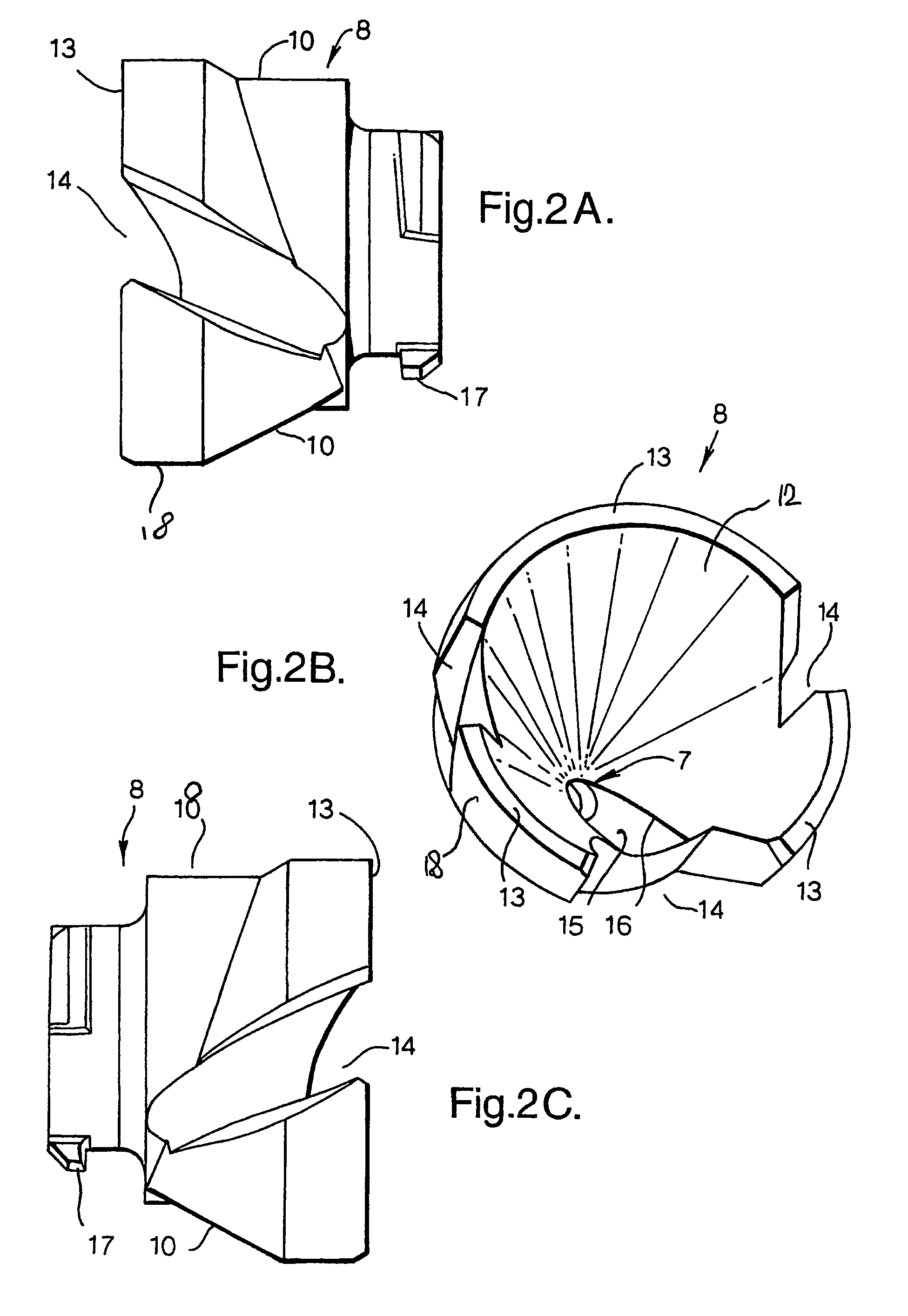
[0019]The present distance holder for the present excavating tool has a wall with a trumpet shaped inner surface section provided with an opening.

[0020]The trumpet shaped inner surface section is suitable to more or less match a heap-shaped bottom profile of the hole. Rotation of the excavating tool inside the hole results in the abrasive jet stream to rotate in the hole such that it is scanned along the hole. When placed over a heap-shaped bottom profile, the distance holder thus provides an improved degree of alignment of the hole bottom profile in front of the rotating abrasive jet stream.

[0021]The opening in the trumpet shaped inner surface section is preferably defined by a recess that is formed in the trumpet shaped inner surface of the wall of the distance holder, whereby the nozzle is arranged to discharge in the recess.

[0022]When placed in the hole in the geological formation over the heap-shaped bottom profile, the recess defines a tunnel for the stream of abrasive fluid t...


PUM


Abstract

The invention features an excavating device for excavating a hole in a geological formation, which excavating device includes:a body rotatable inside the hole along a rotation axis;a nozzle arranged on the body to jet a stream of an abrasive fluid onto a surface in the geological formation in order to generate the hole, wherein the stream has at least an radial velocity component and one parallel to the rotation axis. The excavating device further hasa distance holder arranged on the body to ensure a predefined distance between the nozzle outlet and the surface; whereinthe distance holder has a trumpet shaped inner surface section facing the geological formation, which trumpet shaped inner surface section is provided with an opening for allowing the stream to pass through.The opening in the trumpet shaped inner surface section is defined by a recess that is formed in the inner surface of the wall of the distance holder, whereby the nozzle is arranged to discharge in the recess. The invention also features a distance holder such as described above.

Description

PRIORITY CLAIM AND CROSS REFERENCE[0001]The present application is a 35 U.S.C. 371 national stage filing of PCT / EP2004 / 052677 filed 27 Oct. 2004, which claims benefit of European patent application No. 03104007.4 filed 29 Oct. 2003 and International patent application No. PCT / EP04 / 051407 filed 8 Jul. 2004.FIELD OF THE INVENTION[0002]The invention relates to a distance holder for use as a part of an excavating device.[0003]The invention also relates to an excavating device, for excavating a hole in a geological formation, comprising such a distance holder.BACKGROUND OF THE INVENTION[0004]WO-A-02 / 34653 shows such an excavating device. The described excavating device uses a jet of fluid under pressure in which abrasive particles are mixed to erode the material of a surface in order to generate a hole in said surface. The jet is placed under an angle relative to the advancement direction of the excavating device in the hole, and is rotatably operated inside the hole in order to create t...

Claims


Application Information

Patent Timeline
Patent Type & Authority Patents(United States)
IPC IPC(8): E21B21/12
CPCE21B7/18
Inventor BLANGE, JAN-JETTE
Owner SHELL OIL CO
Learn More