
Powered ramp door lift

a powered lift and ramp door technology, applied in the field of powered ramp door lifts, can solve the problems of cable “unspooling” from the web of the winch, problems such as unspooling, and the use of conventional powered lifts in cargo trailers and other applications with limited success

Inactive Publication Date: 2008-09-02
CARGO SYST
View PDF5 Cites 25 Cited by
  • Summary
  • Abstract
  • Description
  • Claims
  • Application Information

AI Technical Summary

Benefits of technology

"The present invention provides a powered ramp door lift for cargo trailers and other ramp door applications. The lift includes a powered winch assembly, wire cables or nylon straps, and a pusher mechanism. The pusher mechanism prevents the ramp door from unspooling when it is opened. The winch assembly has a cable tension shut off mechanism to prevent unspooling when the ramp door is closed. The lift is easy to install, has a compact design, and can be controlled remotely. The cable tension shut off mechanism ensures safe operation of the ramp door. The technical effects of this invention are consistent and instantaneous operation of the ramp door, increased lifting power, and improved safety."

Problems solved by technology

Heretofore, conventional powered lifts have been used in cargo trailers and other applications with limited success.
One of the major drawbacks of conventional lifts in ramp door applications has been the tendency of the cables to “unspool” from the webs of the winch spool in the absence of cable tension from the winch.
Any differences in cable tension between the two cables results in a slack cable, which leads to unspooling problems.
While cable tension provided by the winch holds the ramp door in the vertical closed position, if the ramp door does not immediately begin to lower with the unwinding of the winch, cable tension is lost.
In the absence of cable tension, the resilient memory of the cables will cause the cables to “unspool” and become tangled or bound in the winch apparatus.
To pull the ramp door open, the user must often be positioned under the lowering ramp door, which creates a potentially hazardous situation.

Method used


Image

  • Powered ramp door lift
  • Powered ramp door lift
  • Powered ramp door lift

Examples


Embodiment Construction

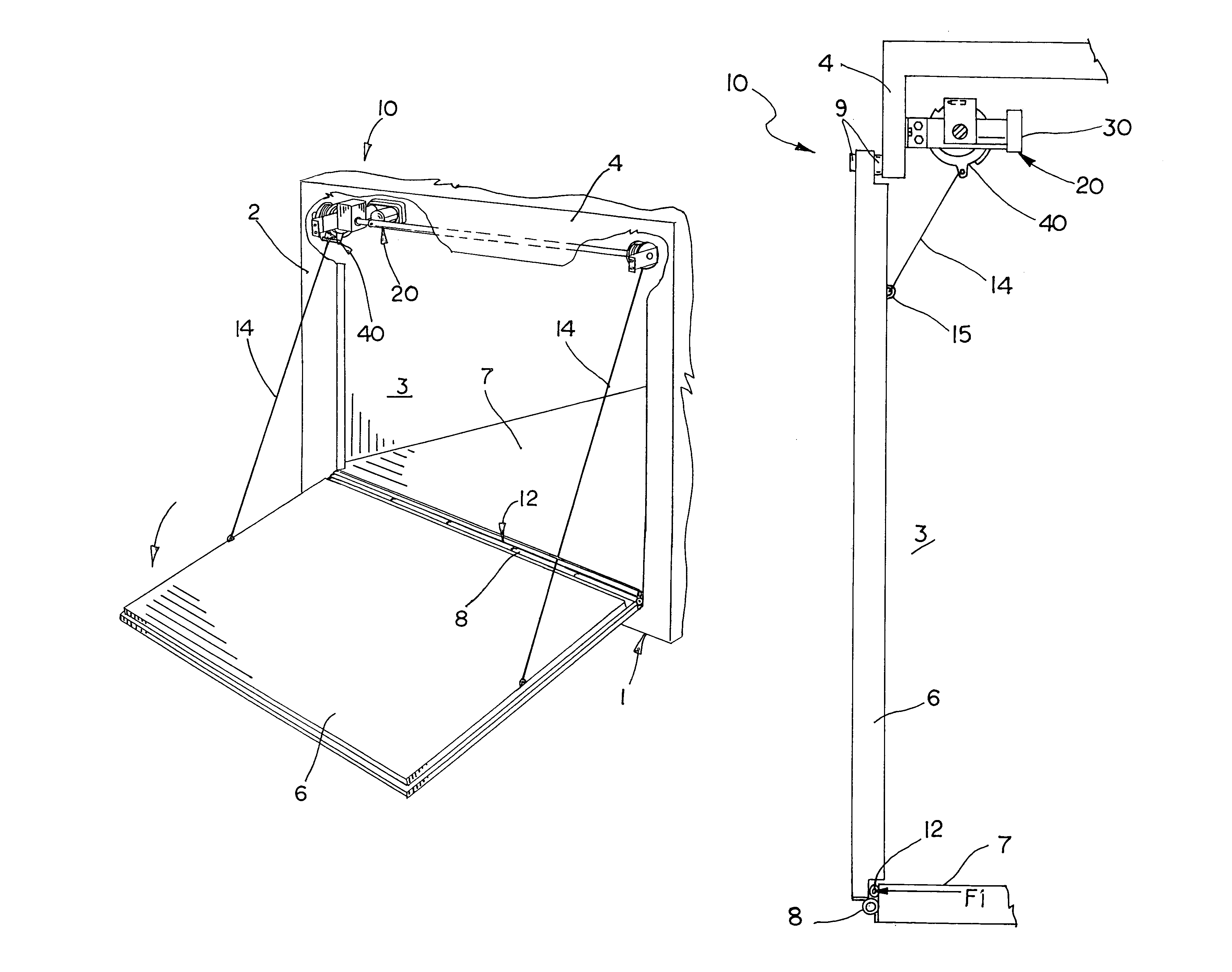
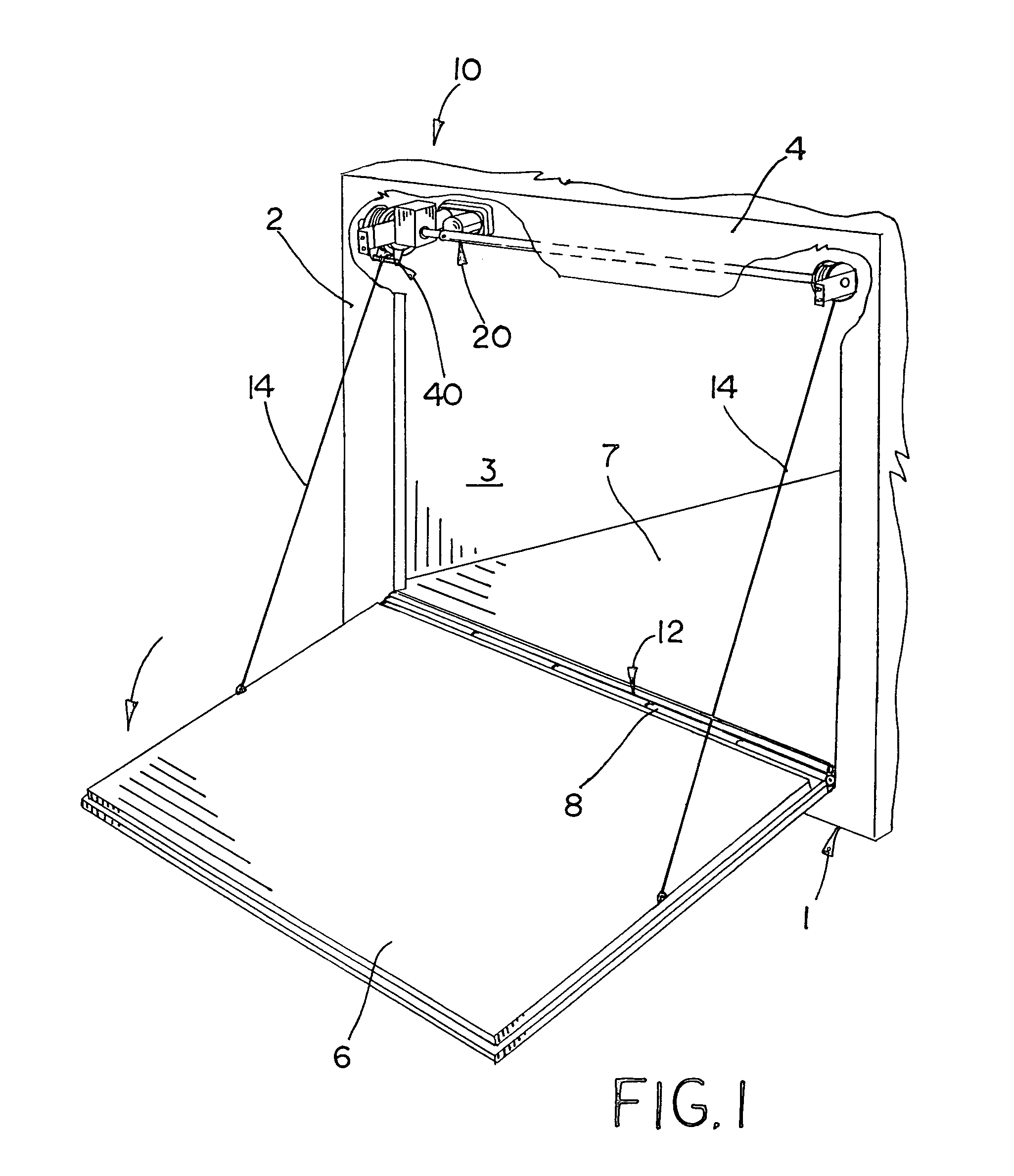
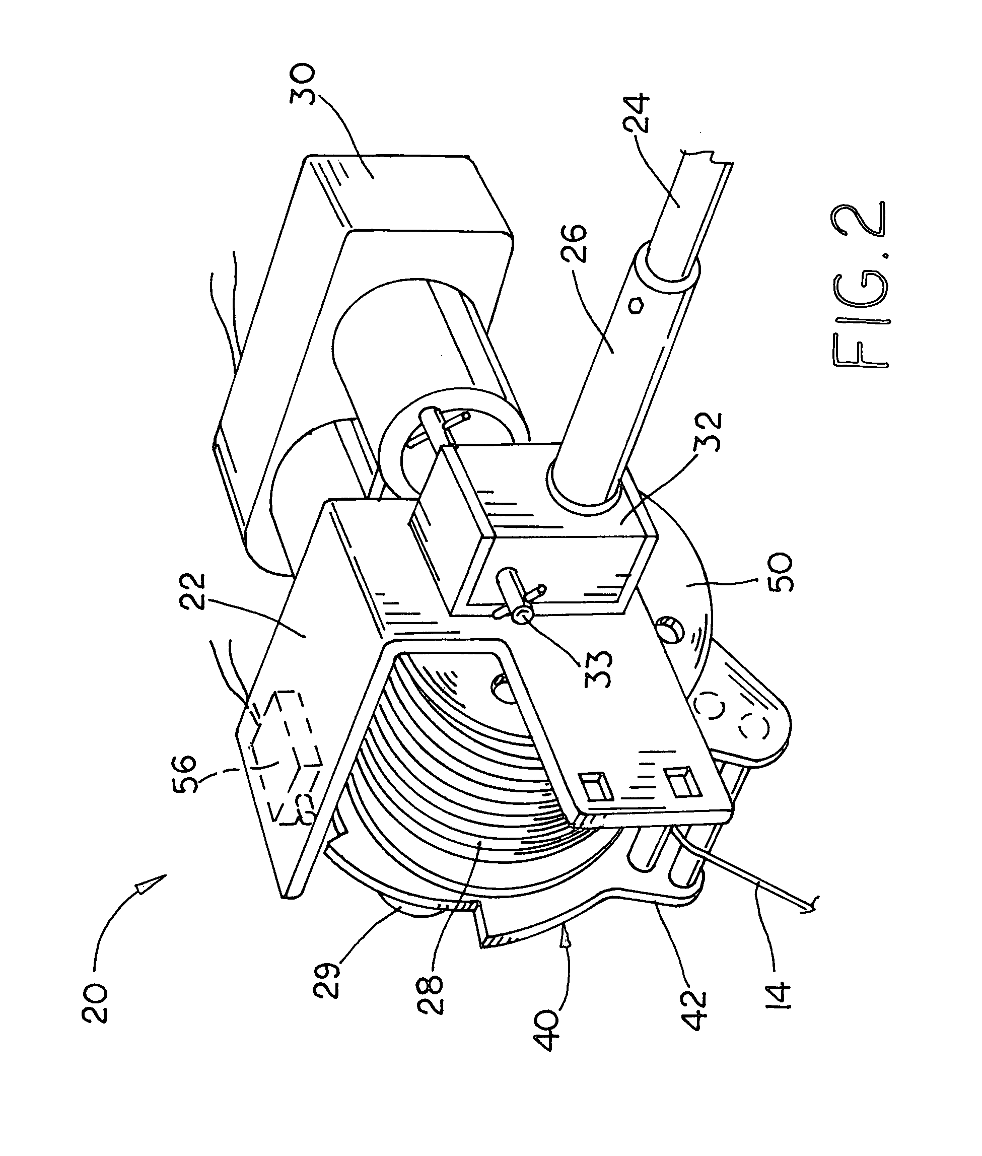
[0028]The powered ramp door lifts embodying the teaching of this invention are designed and intended for use in cargo trailers and other ramp door applications. The powered ramp door lifts raise and lower ramp doors between their open and closed positions. For simplicity of explanation, each embodiment of the powered ramp door lifts is illustrated in the drawings and described herein in a conventional cargo trailer application, although the teaching of this invention can be employed into other ramp door applications. As shown, cargo trailer 1 is of conventional design and includes an end wall 2 having a door opening 3 and a ramp door 6. A hinge 8 pivotally connects the lower edge of ramp door 6 to the trailer floor 7 at the bottom of the door opening 3 which allows the ramp door to swing between a vertical closed position where the door encloses the door opening and an open position in which the upper edge of the ramp door rests on the ground. As shown, ramp door 6 includes a plural...


PUM


Abstract

The powered ramp door lift is used in cargo trailers and other ramp door applications and includes a powered winch assembly, a pair of wire cables or nylon straps connecting the winch assembly to the ramp door, and a “pusher” mechanism. The winch assembly mounted to the trailer header winds and unwinds the cables onto a pair of spools mounted to a drive shaft, which is driven by an electric motor. The “pusher” mechanism prevents the “unspooling” problems that effect the operation of winches in automated ramp door applications. The pusher mechanism engages the ramp door in the closed position and applies an outward force to the ramp door over a small portion of its travel to assist in the initial lowering of the ramp door from the closed position. The winch assembly also includes a cable tension winch shut off mechanism, which deactivates the winch motor in the absence of any tension on cables.

Description

[0001]This invention relates to a powered ramp door lift for use in cargo trailers and other ramp door applications.BACKGROUND OF THE INVENTION [0002]Vertically pivoting ramp doors are common features on cargo trailers, as well as, various types of recreational vehicles and enclosures. Ramp doors are hinged to cargo trailers to allow the ramp doors to swing from a vertical closed position where the ramp door encloses the door opening to an open position where the ramp door contacts the ground, thereby providing a ramp for access to the trailer interior. Powered ramp door lifts used to automatically raise and lower the ramp doors are a highly desirable feature, particularly for applications with large heavy ramp doors. Typically, powered ramp door lifts consist of one or more cables connected to the ramp door and a simple cable winch mounted within the trailer interior. While, simple cable winches winding a single cable can be used to lift the ramp doors in a ramp door application, t...

Claims


Application Information

Patent Timeline
Patent Type & Authority Patents(United States)
IPC IPC(8): B62D33/03
CPCB60P1/435
Inventor COBLE, JOHN R.LINDLEY, DALLIS A.LEFTWICH, WILLIAM B.
Owner CARGO SYST
Learn More