Actuator

a technology of actuators and actuators, applied in the field of actuators, can solve the problems of increasing manufacturing costs, difficult to rotate the polygon mirror at a much higher speed, and difficulty in miniaturizing the size of the apparatus in which the polygon mirror is used, and achieve the effect of large torqu

Inactive Publication Date: 2008-09-02
SEIKO EPSON CORP
View PDF16 Cites 4 Cited by
  • Summary
  • Abstract
  • Description
  • Claims
  • Application Information

AI Technical Summary

Benefits of technology

[0020]Since each of the at least one pair of fixed comb electrodes is adjacent to the corresponding movable comb electrode, it is possible to drive the actuator at low voltage and to operate the movable comb electrodes with large torque. In addition, it is possible to obtain an actuator capable of displacing (or rotating) the movable portion with a large rotational angle (deflection angle). Further, since the actuator is provided with the frame, it is possible to reinforce (and strengthen) the intensity of the actuator.
[0054]Thus, it is possible to provide the actuator capable of operating at low voltage with a high speed and a large deflection angle (amplitude). Further, by having such a structure, it is possible to enlarge the rotational angle (deflection angle) of the movable portion while preventing the amplitude of each of the movable comb electrodes.

Problems solved by technology

However, there is a problem in that it is difficult to rotate the polygon mirror at much higher speed than the speed available at the present.
Further, although a larger motor is required in order to rotate the polygon mirror at higher speed, use of such a larger motor gives rise to a problem in that it is difficult to miniaturize the size of an apparatus in which the polygon mirror is used.
Furthermore, use of such a polygon mirror gives rise to another problem in that the structure of the apparatus becomes necessarily complicated, thus leading to increased manufacturing cost.
Namely, such a single-degree-of-freedom torsional vibrator described above involves a problem in that it is difficult to achieve both of low-voltage driving and large displacement.

Method used


Image

  • Actuator
  • Actuator
  • Actuator

Examples


first embodiment

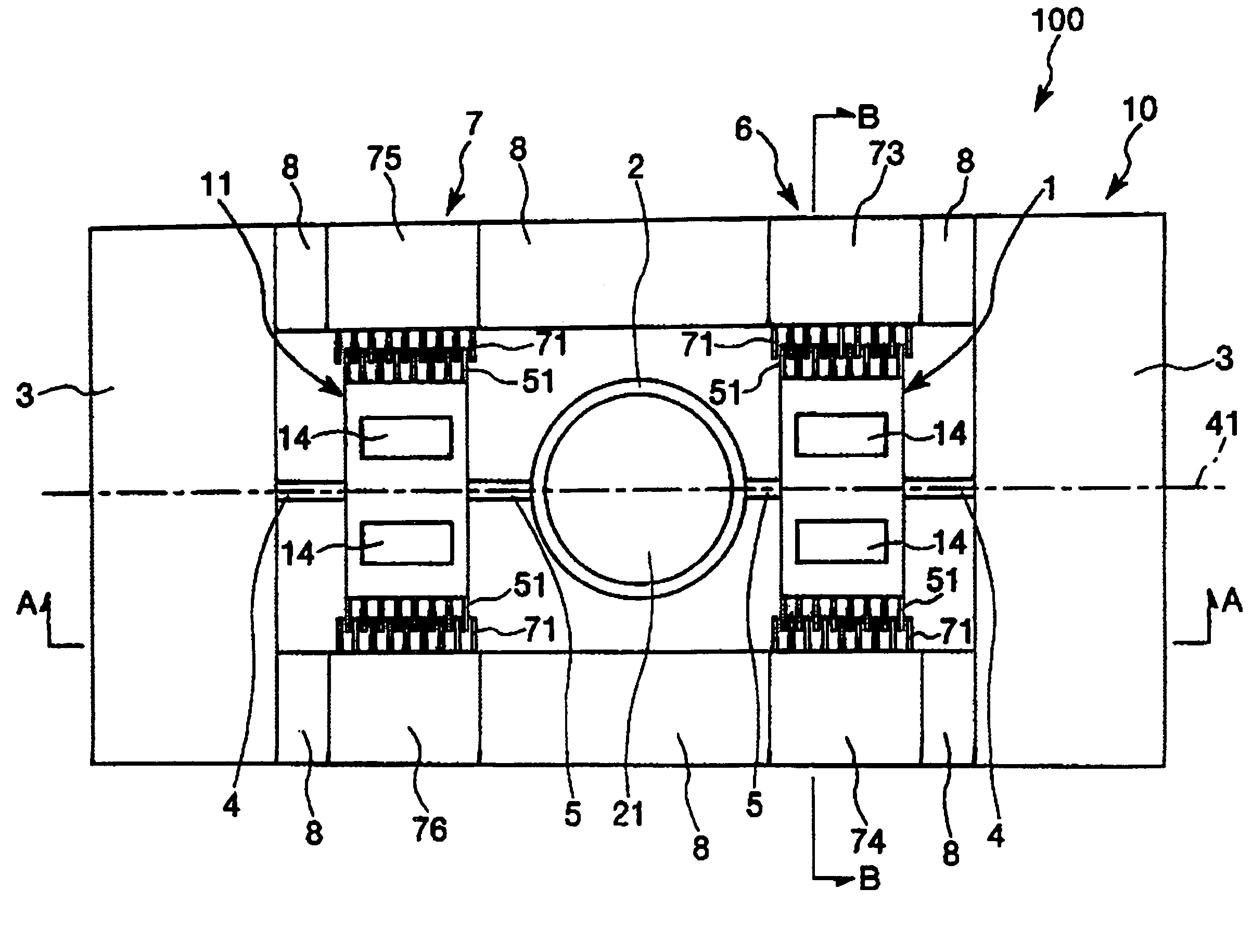
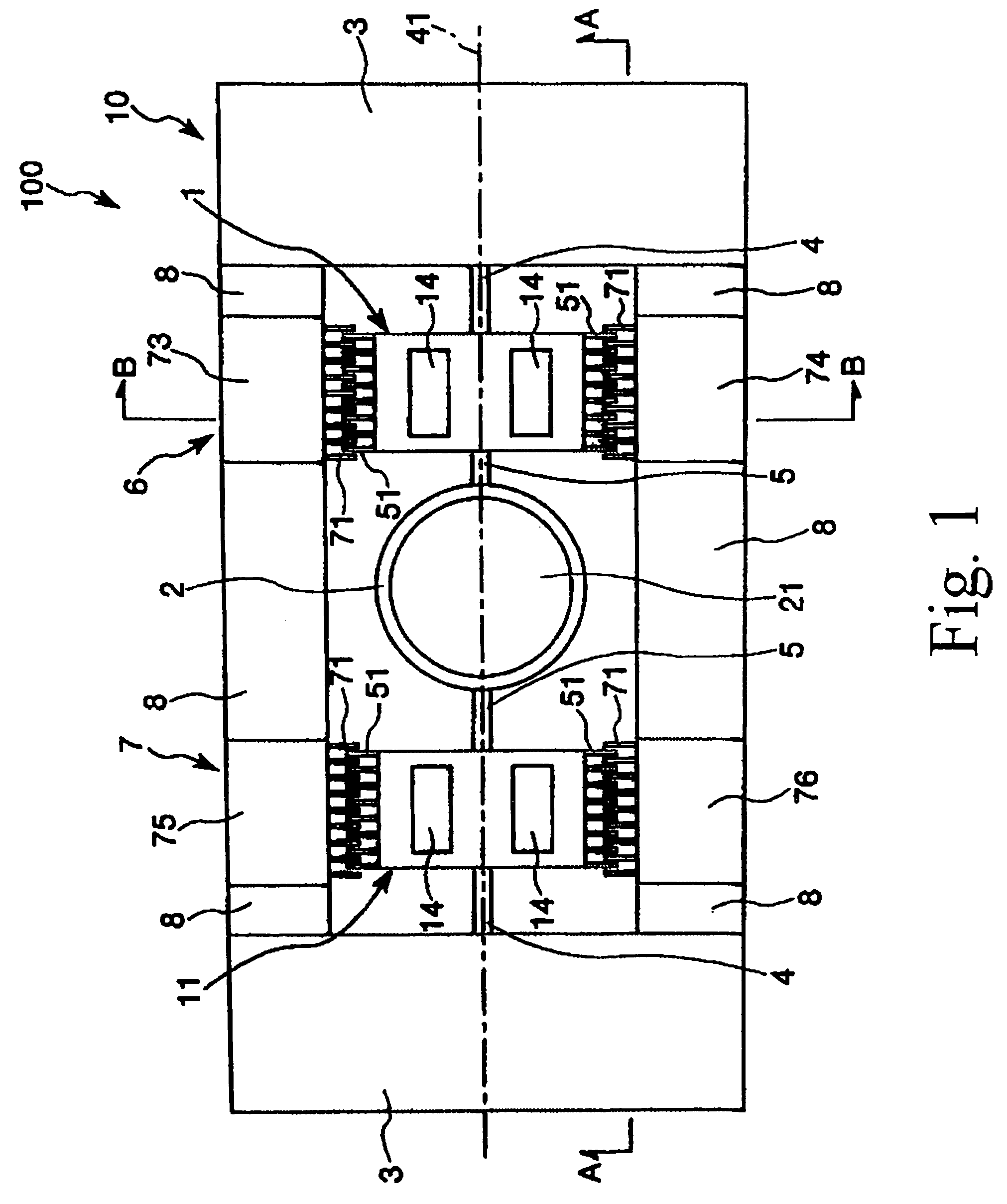
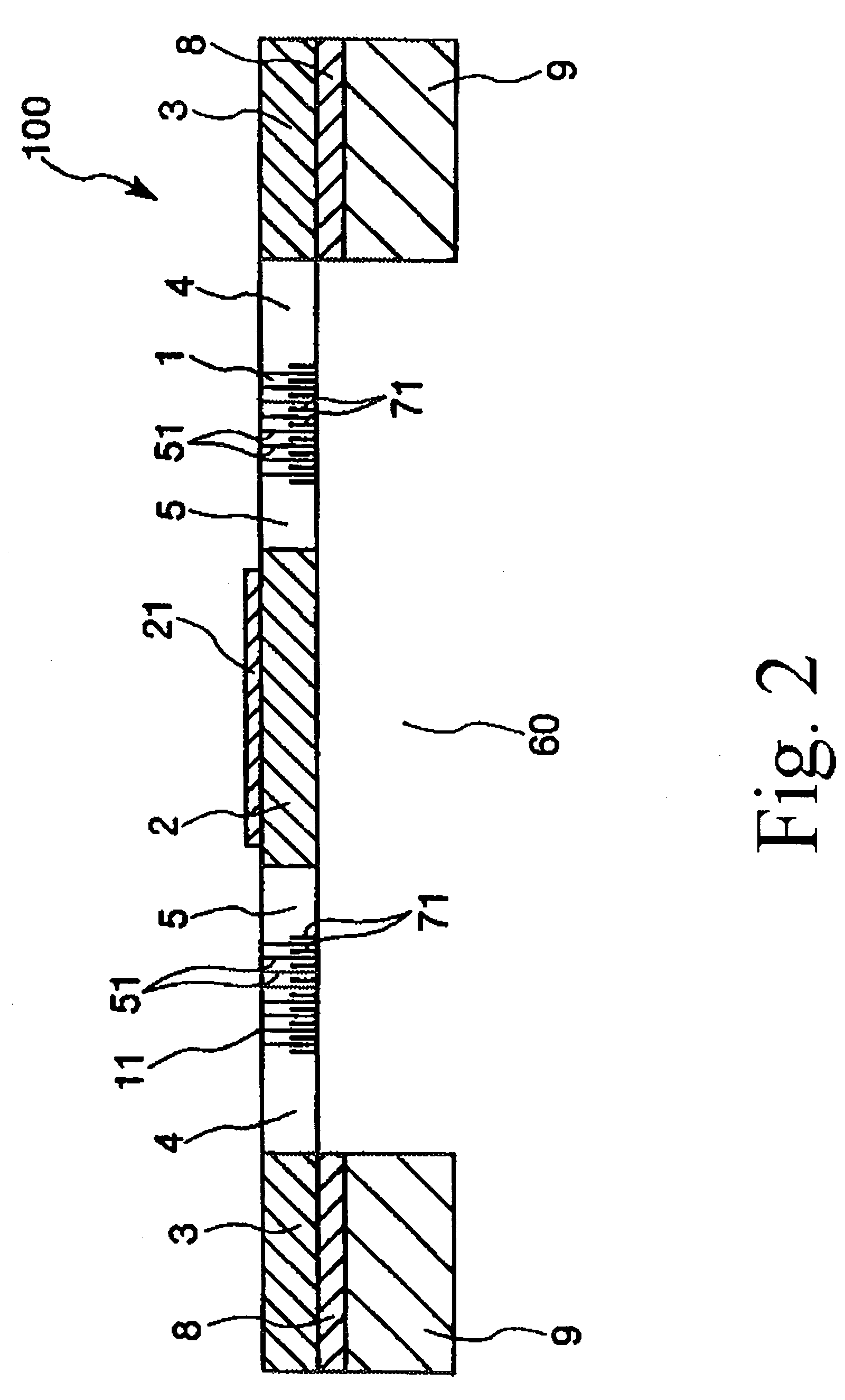
[0079]First, a first embodiment of the actuator according to the invention will be described. FIG. 1 is a plan view which shows a first embodiment of the actuator according to the invention. FIG. 2 is a cross-sectional view taken along line A-A in FIG. 1. FIG. 3 is a cross-sectional view taken along line B-B in FIG. 1. In the following description using FIG. 1, for convenience of description, it is to be noted that the upper side, the lower side, the right side and the left side in FIG. 1 will be referred to as the “upper side”, “lower side”, “right side” and the “left side”, respectively.

[0080]As shown in FIGS. 1 and 2, an actuator 100 includes: a pair of movable comb electrodes (first mass portions) 1 and 11; a movable portion (second mass portion) 2; a pair of supporting portions 3 for supporting the movable portion 2 and the movable comb electrodes 1, 11; four fixed comb electrodes 73, 74, 75 and 76 provided so as to correspond to the pair of movable comb electrodes 1, 11; and a...

second embodiment

[0153]Next, a second embodiment of the actuator according to the invention will be described. FIG. 8 is a plan view which shows the second embodiment of the actuator according to the present invention. Hereinafter, an actuator 100 shown in FIG. 8 will be described by focusing on the difference between the first and second embodiments, and therefore a description of the same points will be omitted.

[0154]As shown in FIG. 8, the actuator 100 of the present embodiment includes two pairs of first elastic connecting portions 4′, 4′, and two pairs of second elastic connecting portions 5′, 5′. The two pairs of first elastic connecting portions 4′, 4′ connect the movable comb electrodes 1, 11 to the supporting portions 3, 3, respectively, so that each of the movable comb electrodes 1, 11 can rotate with respect to the corresponding supporting portion 3. The two pairs of second elastic connecting portions 5′, 5′ connect the movable portion 2 to the movable comb electrodes 1, 11, respectively,...

third embodiment

[0156]Next, a third embodiment of the actuator according to the invention will be described. FIG. 9 is a plan view which shows the third embodiment of the actuator according to the present invention. Hereinafter, an actuator 100 shown in FIG. 9 will be described by focusing on the difference between the first and third embodiments, and therefore a description of the same points will be omitted. In the actuator 100 of the present embodiment, one movable comb electrode 111 is formed around a movable portion 2 in a circular manner. In other words, the movable comb electrode 111 is constructed from a electrode base and a plurality of first electrode teeth 51, and an opening 112 is provided in the movable comb electrode 111 at the center portion thereof. The movable portion 2 is provided within the opening 112 of the movable comb electrode 111.

[0157]With such a structure, the actuator 100 can have a more stable structure. Further, in the present embodiment, the fixed comb electrode 73 an...


PUM


Abstract

An actuator having a rotation central axis includes: an insulative frame; movable comb electrodes having first electrode teeth; a movable portion between the movable comb electrodes; supporting portions on the frame supporting the movable comb electrodes and the movable portion; fixed comb electrodes on the frame corresponding to the movable comb electrodes and provided with second electrode teeth; first elastic connecting portions connecting the movable comb electrodes to the supporting portions so each movable comb electrode can rotate around the rotation central axis; and second elastic connecting portions connecting the movable portion to the movable comb electrodes so that the movable portion can rotate around the rotation central axis. Each movable comb electrode is driven by an alternating voltage between each fixed comb electrode and movable comb electrode. Part of the first electrode teeth overlaps part of the second electrode teeth when no alternating voltage is applied.

Description

CROSS-REFERENCE TO RELATED APPLICATION[0001]This application claims priority to Japanese Patent Application No. 2004-363607 filed Dec. 15, 2004, which is hereby expressly incorporated by reference herein in its entirety.BACKGROUND OF THE INVENTION[0002]1. Field of the Invention[0003]The present invention relates to an actuator, and in particular relates to an actuator of the type employing a two-degree-of-freedom vibration system.[0004]2. Description of the Prior Art[0005]There is known a polygon mirror (rotary polyhedron) as an actuator provided in laser printers, for example. In such a printer, in order to achieve higher-resolution and higher-quality printed output as well as higher-speed printing, it is necessary to rotate the polygon mirror at higher speed. Currently, an air bearing is used to rotate the polygon mirror at high speed with stability. However, there is a problem in that it is difficult to rotate the polygon mirror at much higher speed than the speed available at th...

Claims


Application Information

Patent Timeline
Patent Type & Authority Patents(United States)
IPC IPC(8): H02N1/00G02B26/08
CPCH02N1/002G02B26/0841
Inventor YODA, MITSUHIRO
Owner SEIKO EPSON CORP
Why Eureka
Try Eureka