Video rendering apparatus and method and program

a video and video processing technology, applied in the field of video rendering apparatus and method and video rendering program, can solve the problems of difficult to stably perform, difficult to meet the requirements of a shorter calculation time and higher quality, and difficult to stably calculate subpixel matching between a plurality of frames

Inactive Publication Date: 2008-09-02
KK TOSHIBA
View PDF3 Cites 11 Cited by
  • Summary
  • Abstract
  • Description
  • Claims
  • Application Information

AI Technical Summary

Problems solved by technology

In contrast, the latter is high in theoretical reconstruction accuracy because of the use of the information of a plurality of frames, but needs to calculate matching between a plurality of frames at the subpixel level, which is difficult to stably perform (see, for example, Sung Cheol Park, Min Kyu Park, and Moon Gi Kang, “Super-Resolution Image Reconstruction: A Technical Overview”, IEEE SIGNAL PROCESSING MAGAZINE, May 2003).
That is, it is difficult to satisfy both the requirements of a shorter calculation time and higher quality.
However, it is impossible to stably calculate subpixel matching between a plurality of frames, which is required for the above application.
If the pattern (texture) of an object is homogeneous, or the luminance of the object changes with time, a matching error often occurs.
However, this technique requires a large amount of calculation, and hence is not very suitable for interactive applications.

Method used


Image

  • Video rendering apparatus and method and program
  • Video rendering apparatus and method and program
  • Video rendering apparatus and method and program

Examples


first embodiment

Superimposition of Subsequent Frames

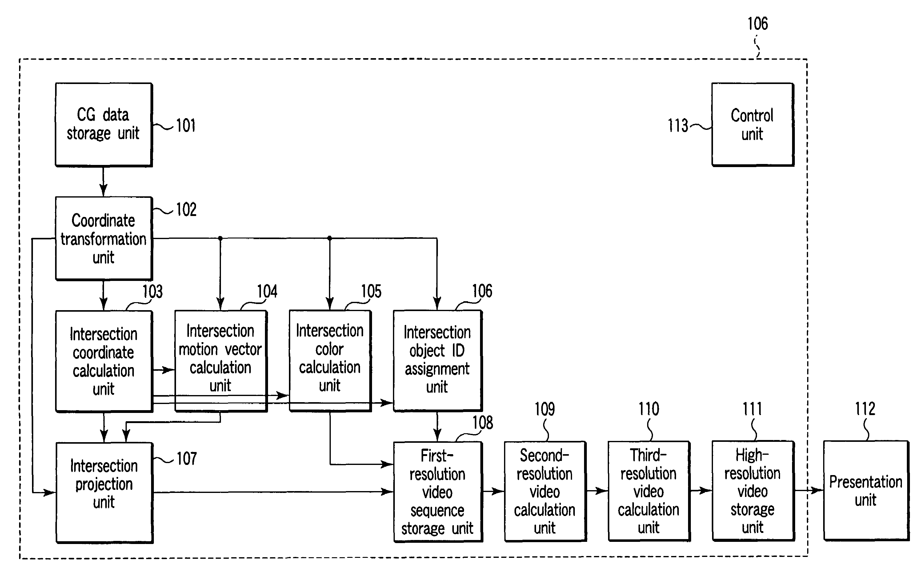
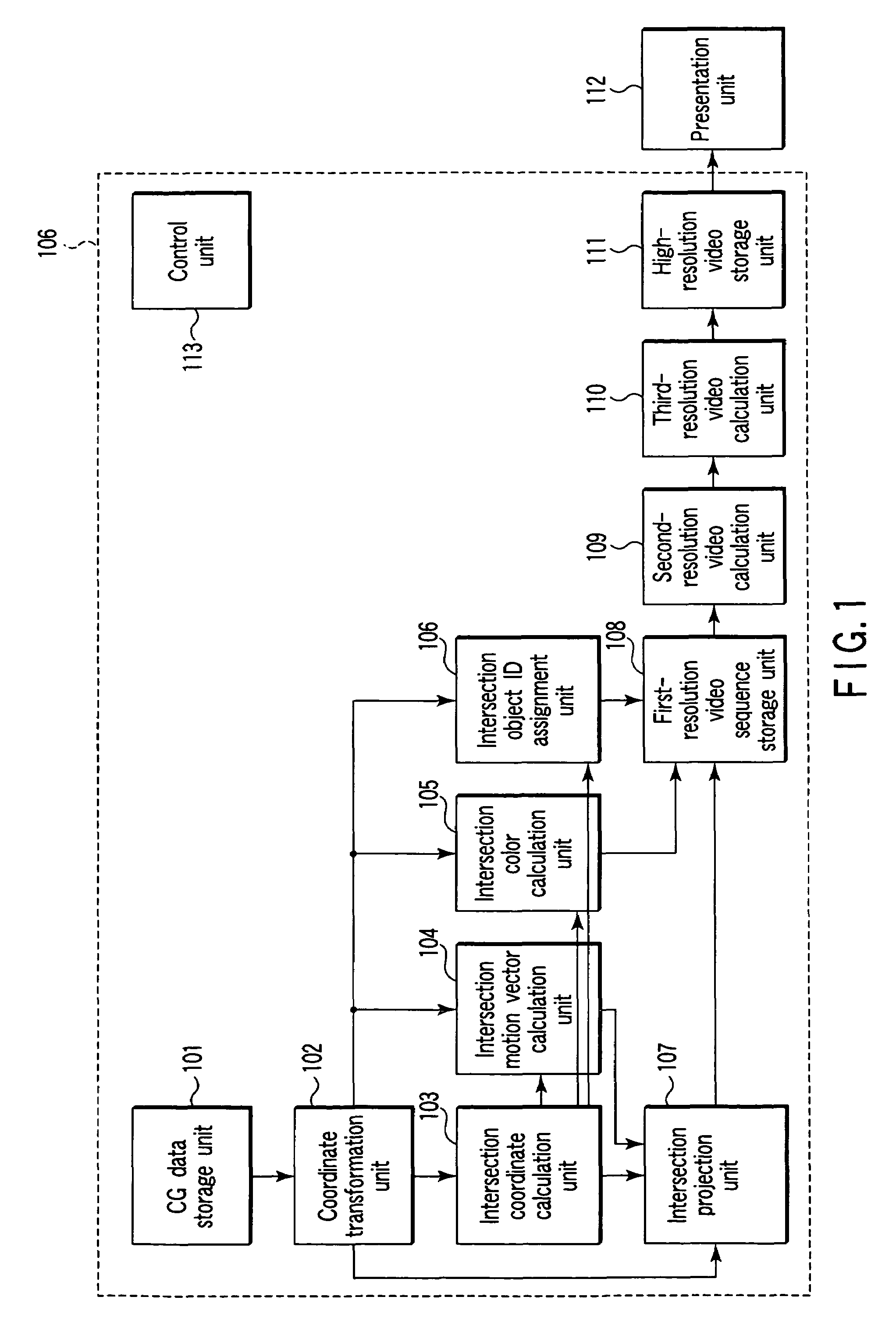
[0060]A video rendering apparatus according to the first embodiment of the present invention will be described with reference to FIG. 1.

[0061]As shown in FIG. 1, the video rendering apparatus according to this embodiment comprises a CG data storage unit 101, coordinate transformation unit 102, intersection coordinate calculation unit 103, intersection motion vector calculation unit 104, intersection color calculation unit 105, intersection object ID assignment unit 106, intersection projection unit 107, first-resolution video sequence storage unit 108, second-resolution video calculation unit 109, third-resolution video calculation unit 110, high-resolution video storage unit 111, presentation unit 112, and control unit 113. Referring to FIG. 1 and subsequent drawings, the presentation unit 112 is not included in the video rendering apparatus, but may be included in it.

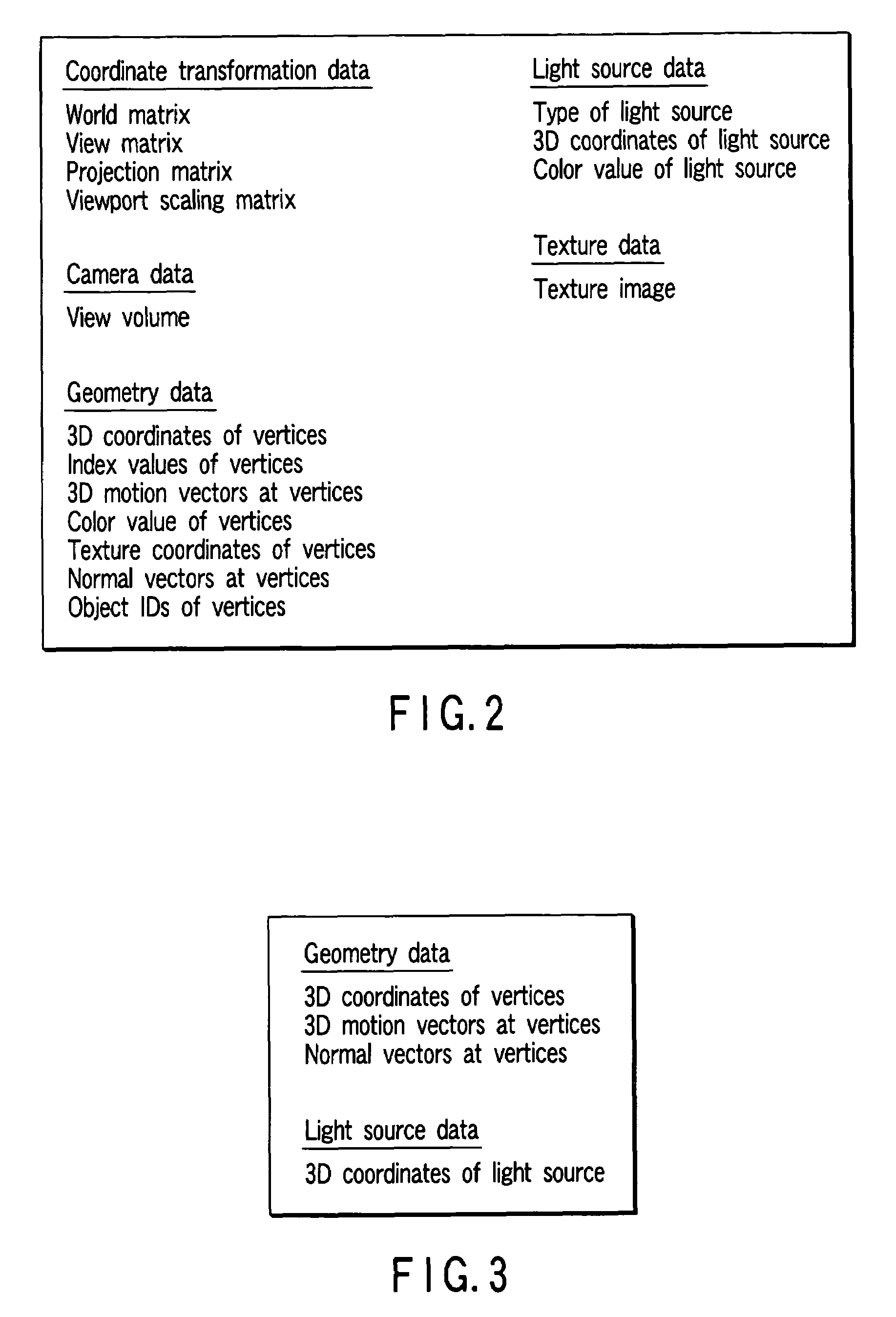
[0062]The CG data storage unit 101 stores CG data comprising data about coordin...

second embodiment

Superimposition of Preceding Frames

[0157]The arrangement of a video rendering apparatus according to the second embodiment is the same as that in the first embodiment shown in FIG. 1. However, the contents of CG data held in a CG data storage unit 101 and the contents of processing in a second-resolution video calculation unit 109 differ from those in the first embodiment. The same reference numerals as those of the units of the apparatus which have been described above denote the same units in the following description, and a description thereof will be omitted.

[CG Data Storage Unit 101]

[0158]As shown in FIG. 18, in this embodiment, the respective vertices in the current frame are assigned in advance a plurality of vectors as attributes, which represent forward motions to the corresponding positions in a plurality of frames temporally succeeding the current frame. These vectors are stored and held in the CG data storage unit 101.

[Second-Resolution Video Calculation Unit 109]

[0159]T...

third embodiment

Superimposition of Preceding and Succeeding Frames

[0167]The arrangement of a video rendering apparatus according to the third embodiment is the same as that of the first embodiment in FIG. 1. However, the contents of CG data held in a CG data storage unit 101 and the contents of processing in a second-resolution video calculation unit 109 differ from those in the first embodiment.

[CG Data Storage Unit 101]

[0168]As shown in FIG. 21, in this embodiment, the respective vertices in the current frame are assigned in advance a plurality of vectors as attributes, which represent backward motions to the corresponding positions in a plurality of frames temporally preceding the current frame, and a plurality of vectors as attributes, which represent forward motions to the corresponding positions in a plurality of frames temporally succeeding the current frame. These vectors are stored and held in the CG data storage unit 101.

[Second-Resolution Video Calculation Unit 109]

[0169]The processing f...


PUM


Abstract

Apparatus includes unit storing CG data containing data about coordinate transformation, camera, geometry, light source, and texture, unit transforming coordinate system of CG data into camera-coordinate system, unit calculating intersections of object and ray vectors passing through sampled points, unit calculating 3D motion vectors, unit calculating color values at intersections, unit assigning object IDs of intersections at 3D coordinates to intersections, unit projecting intersections and 3D motion vectors onto plane, and calculating 2D coordinates at intersections and 2D motion vectors at intersections, unit storing 2D coordinates, 2D motion vectors, color values, and object IDs together as low-resolution video data, unit calculating intermediate-resolution video data by superimposing low-resolution video data of current frame onto low-resolution video data of frames temporally different from current frame, unit calculating high-resolution video data by filtering intermediate-resolution video data, unit storing high-resolution video data, and unit presenting high-resolution video data.

Description

CROSS-REFERENCE TO RELATED APPLICATIONS[0001]This application is based upon and claims the benefit of priority from prior Japanese Patent Application No. 2005-251512, filed Aug. 31, 2005, the entire contents of which are incorporated herein by reference.BACKGROUND OF THE INVENTION[0002]1. Field of the Invention[0003]The present invention relates to a video rendering apparatus and method and a program for the rendering of videos.[0004]2. Description of the Related Art[0005]In computer graphics (CG) rendering, a technique called global illumination is used. Global illumination is a technique for performing illumination calculation in rendering an object in a scene in consideration of the influences of indirect light from other objects around the target object.[0006]Conventional illumination calculation cannot reproduce an effect produced when light reflected by an object illuminates another object, and hence is performed considering that uniform light called ambient light illuminates ...

Claims


Application Information

Patent Timeline
Patent Type & Authority Patents(United States)
IPC IPC(8): G06T15/20G06K9/00G09G5/00G09G5/02G06T15/55
CPCG06T15/50G06T1/00G06T17/00
Inventor KOKOJIMA, YOSHIYUKISUGITA, KAORUSEKINE, MASAHIROMIHARA, ISAOYAMAMOTO, SUMIHIKO
Owner KK TOSHIBA
Why Eureka
Try Eureka