Dual membrane single cavity Fabry-Perot MEMS filter

a fabry-perot mems filter and single cavity technology, applied in the field of dual membrane single cavity fabry-perot mems filter, can solve the problems of reducing the accuracy and precision of wavelength scan, spectral jitter of the passband, and reducing the accuracy of the wavelength scan, so as to achieve the effect of double the total deflection rang

Inactive Publication Date: 2008-09-02
AXSUN TECH
View PDF12 Cites 17 Cited by
  • Summary
  • Abstract
  • Description
  • Claims
  • Application Information

AI Technical Summary

Benefits of technology

[0009]The present invention is directed to a dual membrane, single cavity MEMS Fabry-Perot filter. The Fabry-Perot cavity is defined between two mirror structures that are located on separate MEMS membranes. This configuration can yield a number of advantages. First, the membranes will be typically subject to the same mechanical vibrations, thus, will vibrate together. This vibration, however, will be rejected as common mode, since the two membranes are nominally identical in their electromechanical characteristics. Moreover, since the membranes will move in opposed directions in the gravitational field, the dual membrane device is insulated against passband shifts resulting from changes in orientation in the gravitational field. Finally, since each membrane can now be deflected separately, the total deflection range is effectively doubled without increases in the size of the electrostatic cavities.

Problems solved by technology

These MEMS Fabry-Perot filters, however, have suffered from a number of drawbacks for many applications.
First, they can be sensitive to mechanical vibration that causes the MEMS membrane to vibrate which, in turn, results in spectral jitter of the passband.
This reduces the accuracy and precision of the wavelength scan.
Moreover, these systems can also be susceptible to membrane movement from gravitational acceleration.
Finally, still another problem associated with these MEMS membranes, is a limited scanning range.
Excessive deflection due to excessive drive voltages or electrostatic discharge can cause the membrane to snap down onto the handle wafer.
Many times, this can result in the stiction adhesion of the membrane onto the wafer.
The larger cavity results in higher drive voltages, however.
First, the membranes will be typically subject to the same mechanical vibrations, thus, will vibrate together.

Method used


Image

  • Dual membrane single cavity Fabry-Perot MEMS filter
  • Dual membrane single cavity Fabry-Perot MEMS filter
  • Dual membrane single cavity Fabry-Perot MEMS filter

Examples


Embodiment Construction

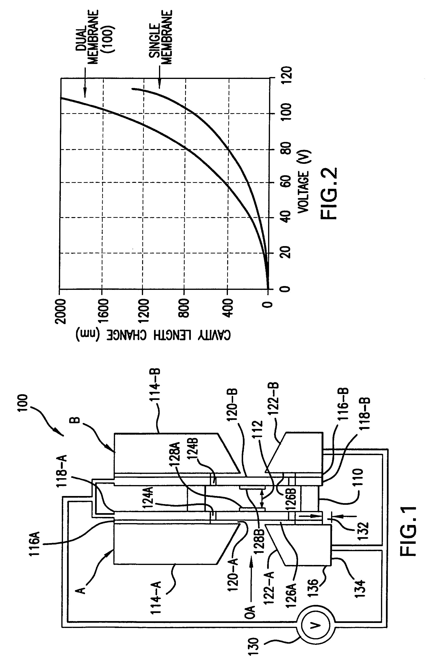
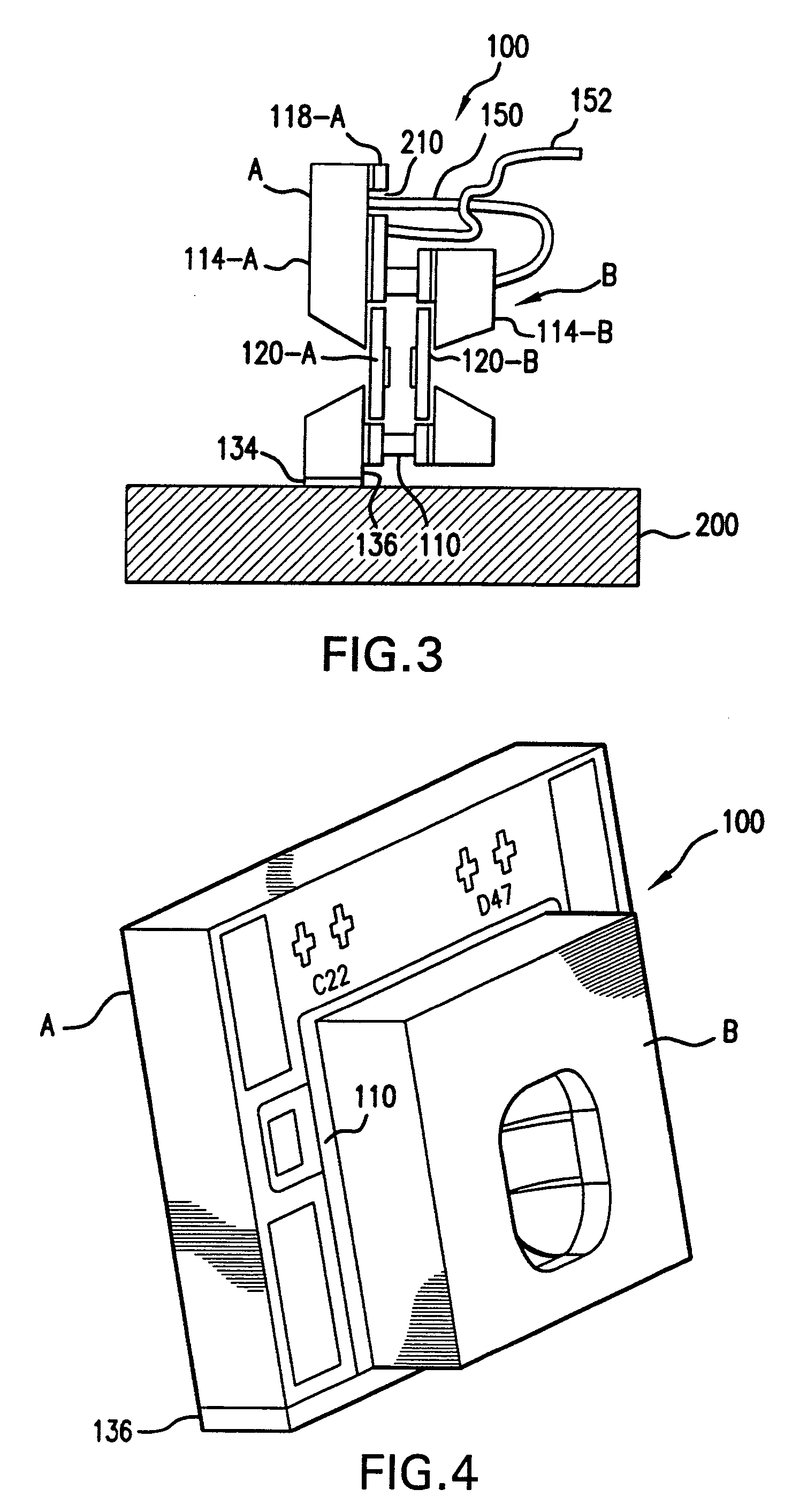
[0018]FIG. 1 shows a dual membrane, single cavity tunable filter 100, which has been constructed according to the principles of the present invention.

[0019]In more detail, the tunable filter 100 comprises a first MEMS membrane device A and a second MEMS membrane device B. These two membrane devices A, B are installed facing each other. An intervening spacer 110 is used to define the optical cavity 112, between the mirror structures of each of these membrane devices A, B.

[0020]In the preferred embodiment, each of the membrane devices is based on the Flanders SOI MEMS membrane device. Specifically, each of the membrane devices A, B includes a handle wafer 114. (Note that the A and B designators after the reference numerals are used to indicate the corresponding membrane device.) A sacrificial oxide layer 116 is used to separate the handle wafer 114 from a device layer 118. A membrane 120 is fabricated in each of the membrane devices A, B by removing the sacrificial release layer 116 f...


PUM


Abstract

A dual membrane, single cavity MEMS Fabry-Perot filter has a cavity that is defined between two mirror structures that are located on separate MEMS membranes. This configuration can yield a number of advantages. First, the membranes will be typically subject to the same mechanical vibrations, thus, will vibrate together. This vibration, however, will be rejected as common mode, however. Moreover, since the membranes will move in opposed directions in the gravitational field, the dual membrane device is insulated against passband shifts resulting from changes in orientation in the gravitational field. Finally, since each membrane can now be deflected separately, the scanning range is effectively doubled without increases in the size of the electrostatic cavities.

Description

BACKGROUND OF THE INVENTION[0001]Micro-electro-mechanical systems (MEMS) Fabry-Perot tunable filters are commercially available. These devices typically combine some sort of deflectable membrane, which, in combination with a fixed mirror, defines the tunable Fabry-Perot cavity. The size of the cavity, and therefore the spectral position of the filter's pass band, is modulated or controlled by deflecting the membrane.[0002]Originally, these MEMS Fabry-Perot tunable filter devices were predominately used in wavelength division multiplexing (WDM) applications for telecommunications. More recently, these MEMS Fabry-Perot filters have been deployed in other applications, such as spectroscopy and medical applications, for example.[0003]U.S. Pat. No. 6,608,711 to Flanders, et al. shows one approach for manufacturing the MEMS Fabry-Perot tunable filter. The Flanders device uses a MEMS membrane that is based on silicon-on-insulator technology. Specifically, the membrane is formed by releasin...

Claims


Application Information

Patent Timeline
Patent Type & Authority Patents(United States)
IPC IPC(8): G02B27/00G01J3/26G02B5/28
CPCG01J3/26
Inventor VERGHESE, PAUL MATTACKAL
Owner AXSUN TECH
Why Eureka
Try Eureka