
Bearing fault signature detection

a fault signature and detection technology, applied in the direction of fluid pressure measurement by mechanical elements, solid-state vibration measurement, amplifier modification to reduce noise influence, etc., can solve the problem of inability to know if the desired process generates the peaks of the vibration spectrum of any sufficiently complex (and actively excited) mechanical system, and energy attenuation

Inactive Publication Date: 2008-09-02
USA AS REPRESENTED BY THE SEC OF THE NAVY THE
View PDF7 Cites 22 Cited by
  • Summary
  • Abstract
  • Description
  • Claims
  • Application Information

AI Technical Summary

Benefits of technology

[0021]The present invention includes a device for detecting the presence of faults developing in rolling element bearings within an apparatus having a means for measuring vibration of an apparatus in operation, a detector for recognizing the signature of rolling el...

Problems solved by technology

Therefore, even though these characteristic fault frequencies are produced inside a bearing with a developing fault, this energy is attenuated as it propagates through the apparatus toward the sensor and is thus undetectable.
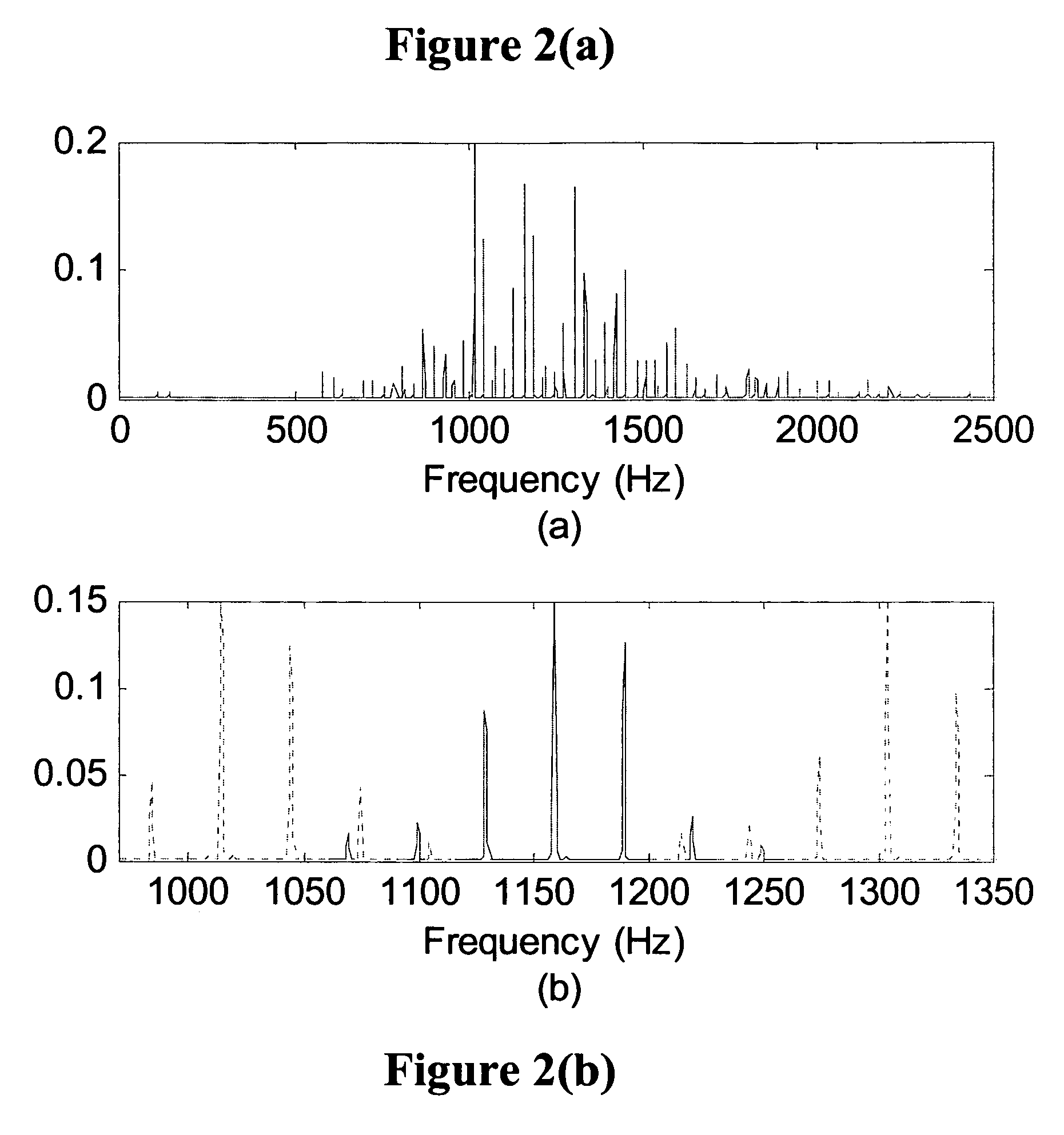
Second, the vibration spectrum of any sufficiently complex (and actively excited) mechanical system is extremely rich with peaks.
However, it is impossible to know if these peaks are generated by the desired process (e.g., a bearing fault) or if they are from multiple unrelated processes and their location in the frequency spectrum is only coincidental.

Method used


Image

  • Bearing fault signature detection
  • Bearing fault signature detection
  • Bearing fault signature detection

Examples

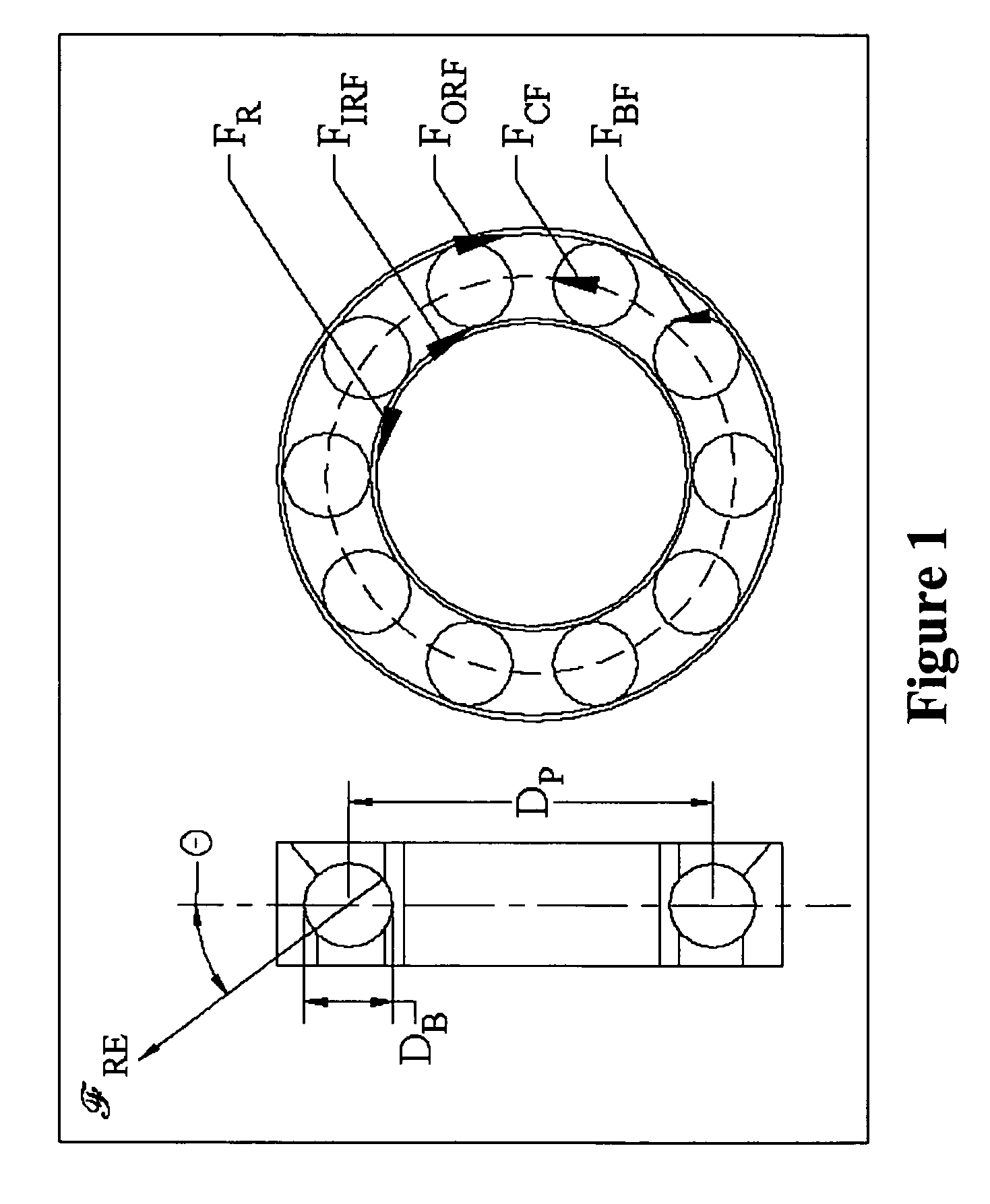

Embodiment Construction

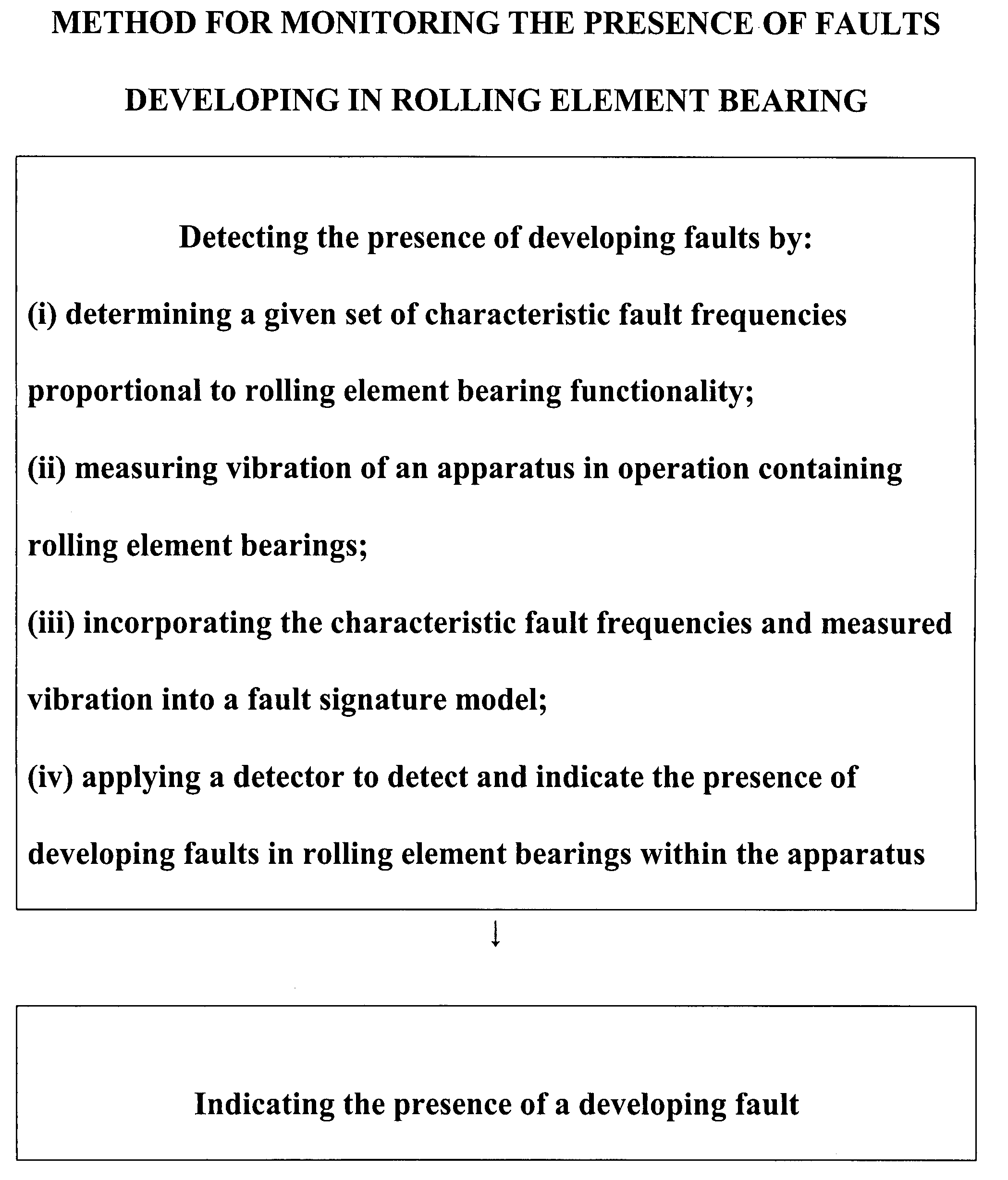
[0029]As detailed herein, the present invention detects the presence of developing faults in rolling element bearings. Detection is accomplished by measuring the vibration of the apparatus in which the bearing is operating (motor, generator, engine, etc.) and searching for signatures unique to bearing faults. These signatures are predicted by a fault signature model and recognized by a detector, both of which are part of the present invention.

[0030]Referring to FIG. 1, the present invention begins with the development of a fault signature model for the production and propagation of the signature from a developing bearing fault. This model is given in (5), shown below, and its derivation and explanation is given in J. R. Stack, T. G. Habetler, and R. G. Harley, “Fault signature modeling and detection of inner race bearing faults,”IEEE Int. Conf. Electric Machines and Drives, San Antonio, Tex., pp. 271-277, May 2005, the disclosure of which is herein incorporated by reference.

{c(n)e−a...


PUM


Abstract

A device, and method, detects the presence of developing faults in rolling element bearings. Detection is accomplished by measuring the vibration of the apparatus in which the bearing is operating (motor, generator, engine, etc.) and searching for signatures unique to bearing faults. These signatures are predicted by a fault signature model and recognized by a detector, both of which are part of this invention.

Description

STATEMENT REGARDING FEDERALLY SPONSORED RESEARCH OR DEVELOPMENT[0001]The invention described herein may be manufactured and used by or for the government of the United States of America for governmental purposes without the payment of any royalties thereon or therefore.BACKGROUND OF THE INVENTION[0002]1. Field of the Invention[0003]The present invention relates to detecting the presence of developing faults in rolling element bearings by measuring the vibration of an apparatus in which bearings are operating and identifying signatures unique to bearing faults. These signatures are predicted by a fault signature model and recognized by a detector.[0004]2. Brief Description of the Related Art[0005]There is an abundance of techniques in the literature designed to detect the characteristic fault frequencies produced by faults in rolling element bearings. A bearing fault will produce one of the four characteristic fault frequencies depending on which bearing surface contains the fault. T...

Claims


Application Information

Patent Timeline
IPC IPC(8): G06F19/00G06F17/30
CPCG01M13/045G01H1/003
Inventor STACK, JASON
Owner USA AS REPRESENTED BY THE SEC OF THE NAVY THE
Learn More